Soil cutting and splitting device at front end of shield machine

A shield machine and soil technology, which is applied in earth drilling, mining equipment, tunnels, etc., can solve the problems of reducing excavation efficiency, tool wear, and instability of earth pressure balance, so as to improve cutting efficiency and prolong service life , to ensure the effect of earth pressure balance

Active Publication Date: 2018-07-03
JINAN RAILWAY TRANSPORT GRP CO LTD
View PDF6 Cites 0 Cited by
  • Summary
  • Abstract
  • Description
  • Claims
  • Application Information

AI Technical Summary

Problems solved by technology

Most of the existing shield machines use the cutter head as a whole to advance forward for soil excavation. During the excavation process, there are large torque when the cutter head rotates and excavation, large soil disturbance in the excavation center area of ​​the cutter head, and shield tunneling axis. If the axial thrust of the cutter head is large, it will easily cause the soil surface above the excavation area to bulge, causing the instability of the soil pressure balance and over-excavation phenomenon, and the poor flow of the soil and the overall solid viscosity are easy to Formation of mud cake during excavation causes tool wear and reduces excavation efficiency

Method used


Image

  • Soil cutting and splitting device at front end of shield machine
  • Soil cutting and splitting device at front end of shield machine
  • Soil cutting and splitting device at front end of shield machine

Examples


Embodiment Construction

[0026] The technical solutions in the embodiments of the present invention will be clearly and completely described below in conjunction with the drawings in the embodiments of the present invention.

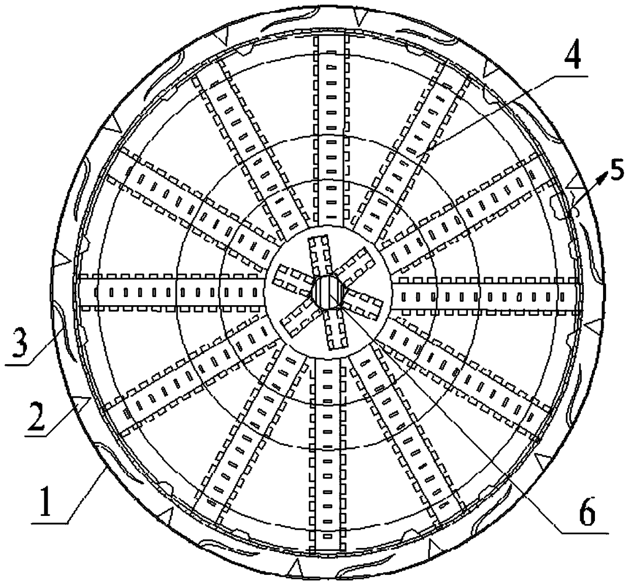
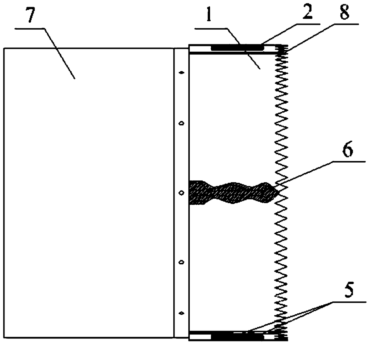
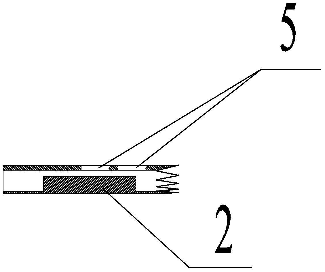
[0027] figure 1 It is a front view of the soil cutting and dividing device at the front end of the shield machine. The dividing device includes a cutter head 4 and a cutting cover 1 arranged around the circumference of the cutter head 4. The cutter head 4 includes a plurality of spokes arranged along the diameter of the cutter head 4. Each A plurality of cutters are arranged on the spokes, and a drill bit 6 is arranged at the center of the cutter head 4, and the drill bit 6 rotates together with the cutter head 4; the cutting cover 1 is annular, and the cutting cover 1 includes two layers of concentrically arranged circles, and the two circles The front part, that is, the part that is in contact with the soil first, is jagged, and the rear of the two circles is provided with 12 ...


PUM


Abstract

The invention discloses a soil cutting and dividing device at the front end of a shield machine and a cutting cover. The former includes a cutter head and a cutting cover arranged around the circumference of the cutter head. The cutter head includes a plurality of spokes arranged along the diameter of the cutter head. Each spoke There are multiple knives on it, and a drill bit in the center of the cutter head; several cutting knives for dividing the soil into blocks and several cutting knives for breaking the blocky soil are arranged in the annular area of ​​the cutting cover. Crushing knife; the beneficial effects of the present invention are: the working surfaces of the inner ring and the outer ring of the cutting cover are jagged, which facilitates the insertion of the cutting cover into the soil body, and the soil body is cut into pieces by using a cutting knife in the annular area, and the sharp The type crushing knife smashes and mixes the soil to increase the fluidity of the soil, reduces the formation of mud cake, protects the cutter on the cutter head, and improves the cutting efficiency; the center drill bit of the cutter head can increase the cutting speed of the cutter head The fluidity of the soil part, and to ensure the normal and stable earth pressure balance of the shield machine, to avoid over-excavation phenomenon.

Description

technical field [0001] The invention relates to the field of tunneling and cutting of a shield machine, in particular to a soil cutting and dividing device and a cutting cover at the front end of a shield machine cutter head. Background technique [0002] The shield machine is a kind of construction machinery equipment used for tunneling. The shield machine cutter head is a key component of the shield machine, mainly used for cutting excavated soil. Most of the existing shield machines use the cutter head as a whole to advance forward for soil excavation. During the excavation process, there are large torque when the cutter head rotates and excavation, large soil disturbance in the excavation center area of ​​the cutter head, and shield tunneling axis. If the axial thrust of the cutter head is large, it will easily cause the soil surface above the excavation area to bulge, causing the instability of the soil pressure balance and over-excavation phenomenon, and the poor flow ...

Claims


Application Information

Patent Timeline
Patent Type & Authority Patents(China)
IPC IPC(8): E21D9/08
Inventor 王国富
Owner JINAN RAILWAY TRANSPORT GRP CO LTD
Why Eureka
Try Eureka