
Bare-concrete corner floating window steel formwork structure body device

A technology of fair-faced concrete and steel formwork, applied in formwork/formwork/work frame, building structure, on-site preparation of building components, etc., can solve the problems of complicated construction of corner bay windows, poor structural force, waste of labor, etc.

Inactive Publication Date: 2015-12-02
刘其标
View PDF0 Cites 10 Cited by
  • Summary
  • Abstract
  • Description
  • Claims
  • Application Information

AI Technical Summary

Problems solved by technology

[0002] The construction of corner bay windows has always been complicated. In the past, most people used wooden formwork for construction. However, due to the complexity of construction, the quality is often not guaranteed, and there are many deviations, which cannot meet the construction requirements. The construction quality defects of some corner bay windows need to be repaired and covered by decoration, the structural strength is poor, and a lot of labor is wasted; aluminum alloy formwork, national standard steel formwork and all-steel large formwork have not been seen to make corner bay windows, nor have I seen this For this reason, it is urgent to develop a practical tool that can improve the construction quality of corner bay windows and reduce labor costs.

Method used


Image

  • Bare-concrete corner floating window steel formwork structure body device
  • Bare-concrete corner floating window steel formwork structure body device
  • Bare-concrete corner floating window steel formwork structure body device

Examples


Embodiment Construction

[0050] In order to further illustrate the above-mentioned purpose, technical scheme and effect of the present invention, the present invention will be described below in conjunction with the accompanying drawings and relevant known technical knowledge through the embodiments:

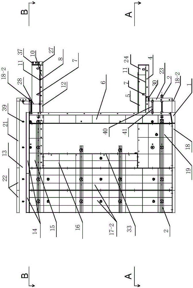
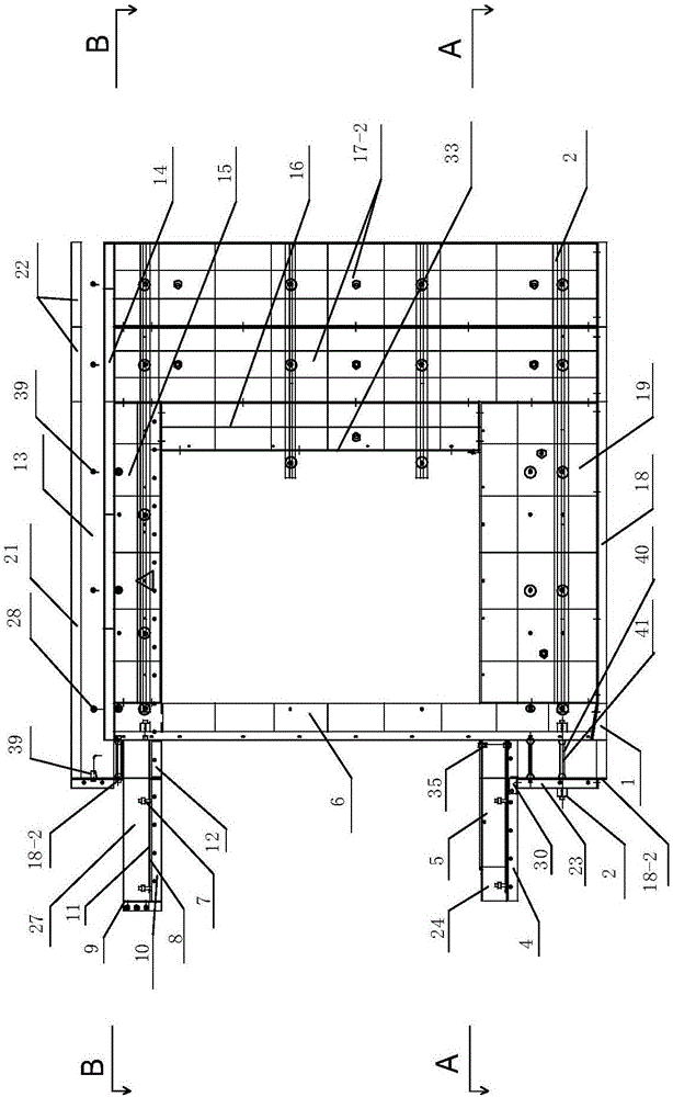
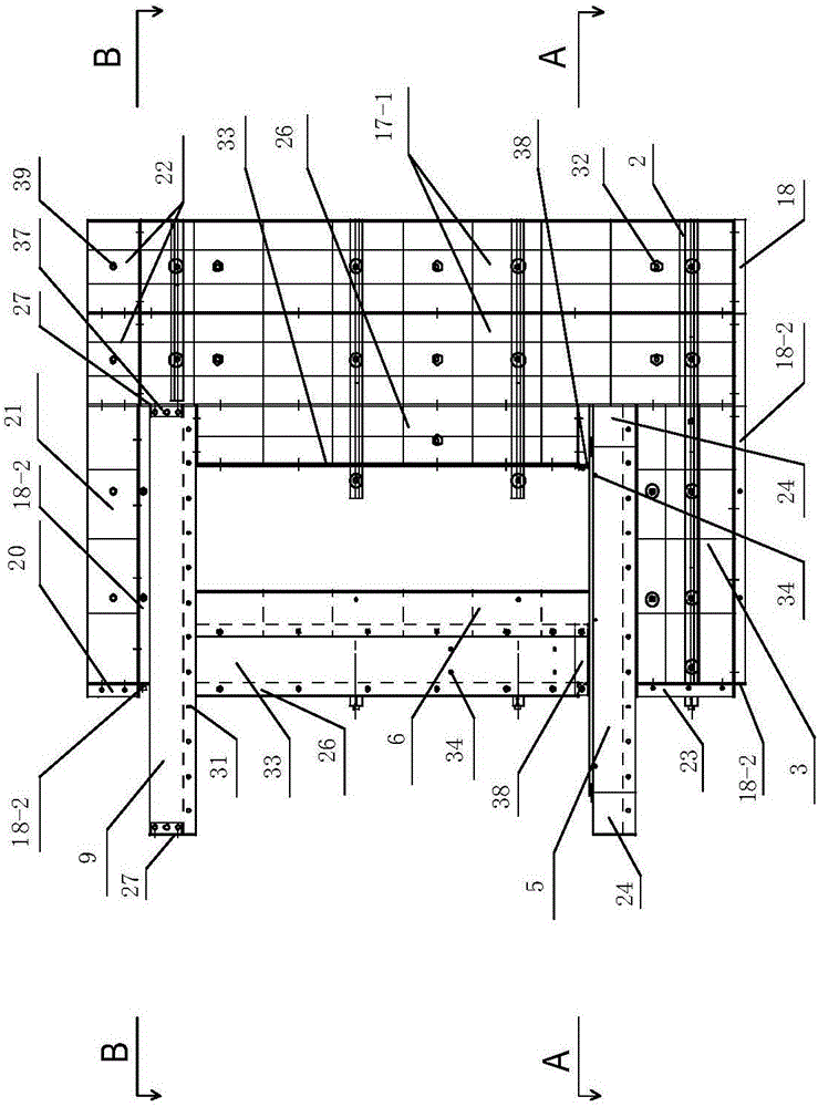
[0051] Such as Figure 1-6As shown, this kind of fair-faced concrete corner bay window steel formwork structure includes an inner wall main formwork 17-2, an outer wall main formwork 17-1, an outer wall joint formwork 22, a floor steel formwork 14, and a footing 18; this structure Also include inner corner mold 6, window inner mold 16, window outer mold 26, lower window inner mold 19, lower window outer mold 3, lower floating bottom mold 4-1, lower floating bottom mold 4-2, upper floating bottom mold 10 -1, upper floating bottom mold 10-2, window beam bottom mold 12, window beam inner mold 15, window beam outer mold 21, bay window hole mold 33, upper floating enclosure mold 9, upper floating head enclos...


PUM


Abstract

The invention relates to a bare-concrete corner floating window steel formwork structure body device. The device is characterized in that an internal corner formwork stretching to the top is arranged at the corner, and on the lower portion of the internal corner formwork, an under-window inner formwork, an under-window outer formwork and lower floating bottom formworks are assembled to be connected with an inner-wall universal main formwork and an outer-wall universal main formwork through the internal corner formwork; one side faces of two window inner formworks and one side faces of two window outer formworks are connected with the inner-wall main formwork and the outer-wall main formwork arranged on the two sides of a window respectively; the bottom edges of two floating window hole formworks suspend at the height same as that of the lower faces of the window inner formworks and connected with the other side faces of the window inner formworks and the window outer formworks; on the upper portion of the internal corner formwork, a window beam inner formwork, a window beam outer formwork, a window beam bottom formwork and upper floating bottom formworks are assembled to be connected with the inner-wall universal main formwork and the outer-wall universal main formwork through the internal corner formwork. Due to the fact that the device adopts the internal corner formwork stretching to the top, assembly of a corner floating window steel formwork is facilitated; according to the device, concrete can be successfully poured into an integral structure body for once, and therefore the anti-shock effect is enhanced; the steel formwork is high in universality and comprehensive in function and can meet requirements of various structures.

Description

technical field [0001] The invention relates to building construction equipment, in particular to a steel formwork structure device for clear-water concrete corner bay windows. Background technique [0002] The construction of corner bay windows has always been complicated. In the past, wooden formwork was used most often for construction. However, due to the complexity of construction, the quality is often not guaranteed, and there are many deviations, which fail to meet the construction requirements. The construction quality defects of some corner bay windows need to be repaired and covered by decoration, the structural strength is poor, and a lot of labor is wasted; aluminum alloy formwork, national standard steel formwork and all-steel large formwork have not been seen to make corner bay windows, nor have I seen this For this reason, there is an urgent need to develop a practical tool that can improve the construction quality of corner bay windows and reduce labor costs....

Claims


Application Information

Patent Timeline
IPC IPC(8): E04G15/02
Inventor 刘其标
Owner 刘其标
Learn More