A sludge crushing and drying equipment
A technology for sludge and equipment, which is applied in the field of sludge crushing drying equipment, can solve problems such as deficiencies, and achieve the effects of high energy utilization rate, uniform drying process, and good drying effect
- Summary
- Abstract
- Description
- Claims
- Application Information
AI Technical Summary
Problems solved by technology
Method used
Image
Examples
Embodiment 1
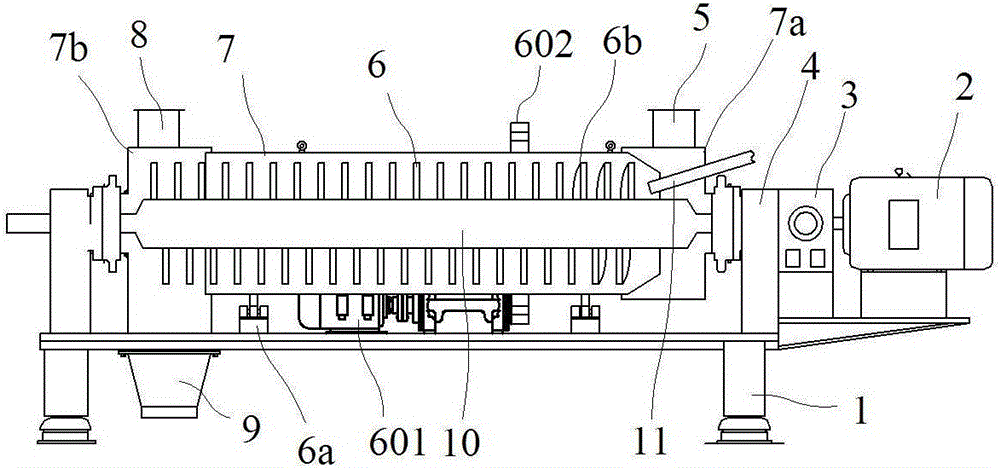
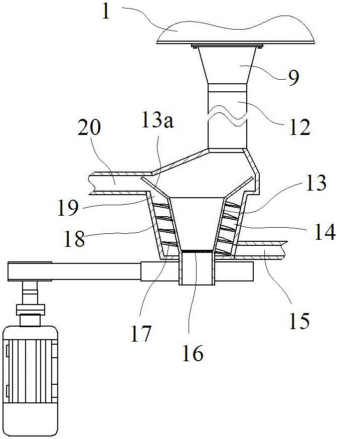
[0023] Such as figure 1In the shown embodiment, a sludge crushing type drying equipment includes a drying main cylinder 7, a frame 1 and a rotor main shaft 10, the drying main cylinder is placed horizontally on the frame, and the frame is placed on the drying main The two ends of the barrel are respectively provided with bearing seats 4 for positioning the main shaft of the rotor. One end of the drying main cylinder is provided with a feed end 7a, and the other end is provided with a discharge end 7b. The drying main cylinder can rotate relative to the feed end and the discharge end, and is positioned on the frame by the support roller 6a. The top of the feed end is provided with a hot flue gas inlet 5, and the top of the discharge end is provided with a wet flue gas outlet. The frame is provided with a bearing seat for positioning the rotor main shaft, the main shaft drive motor 2 and the main cylinder drive motor 601 are provided on the frame, and the reducer 3 is also arra...
Embodiment 2
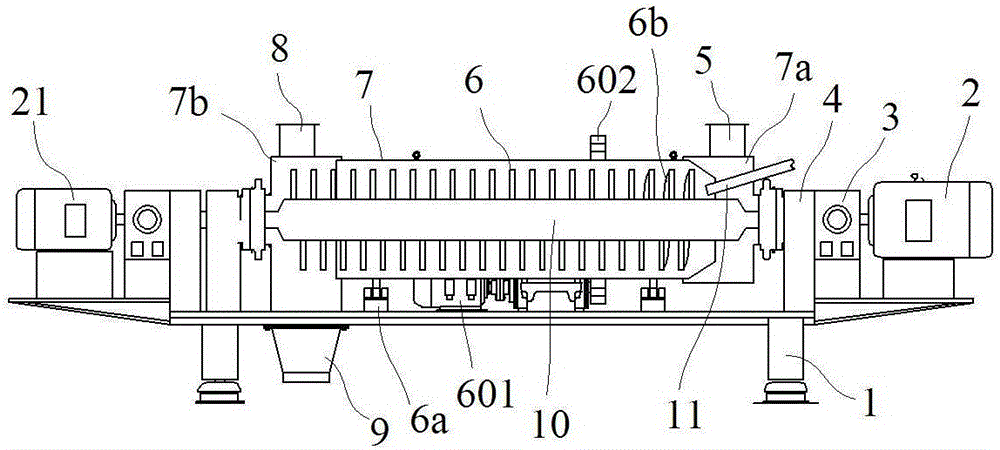
[0027] The basic structure and implementation mode of this embodiment are the same as embodiment 1, and its difference is, as image 3 , Figure 4 As shown, the frame is provided with a mud-beating motor 21, and the mud-beating motor is located at the end of the rotor main shaft away from the main shaft driving motor. One end of the transmission inner shaft is connected with the output shaft of the mud-beating motor, and the other end is matched with the inner shaft bearing. The rotor main shaft is provided with a plurality of mud-beating devices, including a mud-beating ball 24, a stopper 28, a ball receiving spring 27, a slide rod 25, and a slide hole arranged on the main shaft wall. The ball and the limiting part are respectively connected with the two ends of the slide bar, the ball receiving spring is sleeved on the slide bar and is located between the limit part and the inner wall of the rotor main shaft, the mud ball is in contact with the outer side wall of the rotor ...
PUM
 Abstract
Description
Claims
Application Information
 - R&D
- Intellectual Property
- Life Sciences
- Materials
- Tech Scout
- Unparalleled Data Quality
- Higher Quality Content
- 60% Fewer Hallucinations
Browse by: Latest US Patents, China's latest patents, Technical Efficacy Thesaurus, Application Domain, Technology Topic, Popular Technical Reports.
© 2025 PatSnap. All rights reserved.Legal|Privacy policy|Modern Slavery Act Transparency Statement|Sitemap|About US| Contact US: help@patsnap.com


