
Folding propeller with limiting structures

A technology of limiting structure and blade, applied in the field of aviation devices, can solve the problems of easy horizontal movement of the blade, difficult to deploy and start the blade, affecting storage and transportation, etc., so as to improve the flight safety factor, reduce the risk of take-off failure, simple structure

Inactive Publication Date: 2015-11-25
ANYANG HAOKE TECH DEV CO LTD
View PDF6 Cites 19 Cited by
  • Summary
  • Abstract
  • Description
  • Claims
  • Application Information

AI Technical Summary

Problems solved by technology

[0002] Folding propellers are widely used in aircraft due to their convenient storage and transportation, and reliable work after unfolding according to requirements. At present, the traditional installation mechanism of folding propellers mainly includes propeller clips and shafts (the shafts are usually replaced by screws), among which the propeller The clip is installed on the power shaft of the aircraft. The two ends of the propeller clip are U-shaped openings. There are fixed shafts or rotating shafts in the up and down direction at the U-shaped openings of the propeller clips. The fixed shaft or rotating shaft is usually replaced by a long screw. It is used to install the propeller. There is a shaft hole at the root of the propeller. Under the restriction of the propeller clamp, the propeller cannot swing up and down, but can only swing left and right in the horizontal direction of the U-shaped opening. The propeller can be folded during transportation and storage to reduce the occupied space. Space, convenient for storage and transportation. When working, the power shaft of the aircraft drives the paddle clamp to rotate, and the paddle clamp drives the blade to rotate. When the rotation speed is large enough, the blade will work normally after being unfolded under the action of centrifugal force. In this structure, The paddle clamp needs to have a suitable clamping force on the blade. At present, the clamping force of the root of the blade in the traditional mechanism depends on the long screw top as the shaft to clamp the blade. If the long screw is too tight, then The propellers will not be easy to unfold and start during flight, which will lead to take-off failure and many adverse consequences. Even if the long screws are too tight after deployment, they will easily vibrate during work, and even damage the propellers in severe cases. The vibration of the aircraft It is one of the major fatal problems, which can lead to negative effects such as flight failure, falling, and significantly shortened equipment life. If the screws are too loose, the blades will easily move horizontally and affect storage and transportation.

Method used

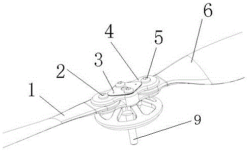
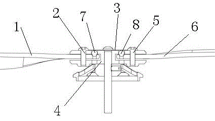
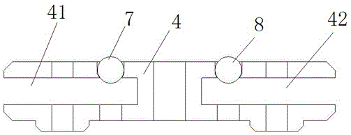

Image

  • Folding propeller with limiting structures
  • Folding propeller with limiting structures
  • Folding propeller with limiting structures

Examples


Embodiment Construction

[0014] In order to more fully explain the implementation of the present invention, implementation examples of the present invention are provided. These implementation examples are only illustrations of the present invention, and do not limit the scope of the present invention.

[0015] The present invention will be further described in detail in conjunction with the accompanying drawings. Each mark in the accompanying drawings is: Each mark in the accompanying drawings is: 1: left blade; 2: left vertical shaft; 3: elastic steel sheet; 4: oar clip; 41: Left U-shaped opening; 42: Right U-shaped opening; 43: Left long gap; 44: Right long gap; 5: Right vertical shaft; 6: Right propeller; 61: Positioning slot one; 62: Positioning slot two; 63: Positioning groove three; 601: positioning pit one; 602: positioning pit two; 603: positioning pit three; 7: left positioning bead; 8: right positioning bead; 9: power shaft; 10: left positioning slider; 101 : Left positioning slider handle;...


PUM


Abstract

The invention discloses a folding propeller with limiting structures and belongs to the technical field of aviation devices. The folding propeller with the limiting structures comprises a propeller clamp and propeller blades, wherein the propeller blades are rotationally connected with two sides of the propeller clamp, propeller blade limiting structures are arranged on the folding propeller, U-shaped openings are formed in tail ends of two sides of the propeller clamp in the horizontal direction, roots of the propeller blades are rotationally arranged in the U-shaped openings through a vertical shaft, and each propeller blade limiting structure is arranged between the propeller clamp and the corresponding propeller blade. In the transportation process, the folding propeller can keep a folding state reliably, various problems caused by swinging of the propeller blades in the transportation process are prevented, the folding propeller can be in an unfolding state reliably during flying through the limiting structure as is required, smooth take-off is guaranteed, and the folding propeller with the limiting structures has a good technical effect.

Description

technical field [0001] The invention relates to a folding paddle, in particular to a folding paddle with a limiting structure, and belongs to the technical field of aviation devices. Background technique [0002] Folding propellers are widely used in aircraft due to their convenient storage and transportation, and reliable work after unfolding according to requirements. At present, the traditional installation mechanism of folding propellers mainly includes propeller clips and shafts (the shafts are usually replaced by screws), among which the propeller The clip is installed on the power shaft of the aircraft. The two ends of the propeller clip are U-shaped openings. There are fixed shafts or rotating shafts in the up and down direction at the U-shaped openings of the propeller clips. The fixed shaft or rotating shaft is usually replaced by a long screw. It is used to install the propeller. There is a shaft hole at the root of the propeller. Under the restriction of the prop...

Claims


Application Information

Patent Timeline
IPC IPC(8): B64C11/28
Inventor 牛晓斌李庆丰魏建义施安祥
Owner ANYANG HAOKE TECH DEV CO LTD
Learn More