a regulator
A regulator and rotary adjustment technology, applied in control/adjustment systems, instruments, control components, etc., can solve the problems of large occupied area, cumbersome installation, complex structure, etc., and achieve small occupied area, simple and convenient installation, and structure. compact effect
- Summary
- Abstract
- Description
- Claims
- Application Information
AI Technical Summary
Problems solved by technology
Method used
Image
Examples
Embodiment 1
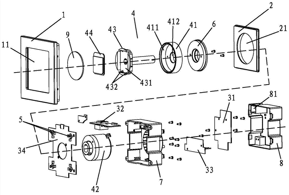
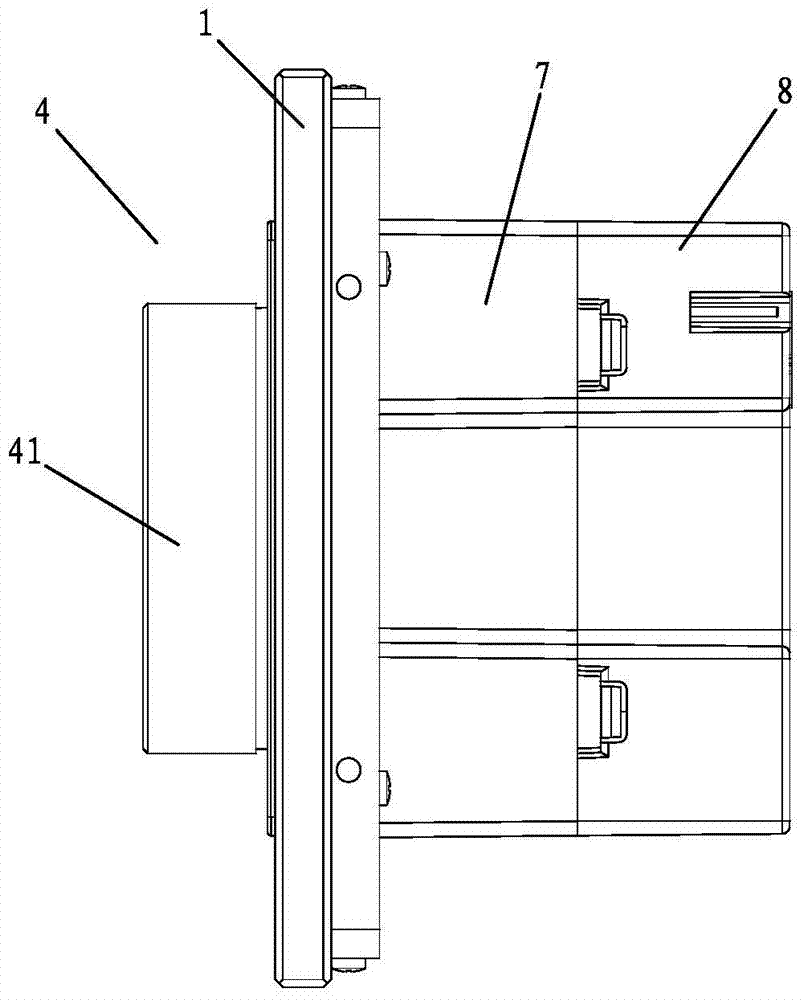
[0023] see figure 1 and figure 2 , this embodiment includes a frame 1, a panel 2 mounted on the frame 1, a control circuit board and a rotation adjustment mechanism 4, the frame 1 is provided with a through slot 11, and the panel 2 is slidably sleeved in the through slot 11; the control circuit board is fixedly installed on the frame 1, a switch is arranged on the control circuit board, and the switch is in contact with the panel 2; the panel 2 has a through hole 21, so One end of the rotation adjustment mechanism 4 passes through the panel 2 and extends out of the through hole 21, and the rotation adjustment mechanism 4 is electrically connected with the control circuit board. The present invention can trigger the control circuit board to perform different functions by pressing different positions around the panel 2, such as on / off, high / small wind speed, cooling / heating, etc., integrating the functions of knob rotation adjustment and pressing adjustment, and the structure ...
Embodiment 2
[0031]This embodiment is based on Embodiment 1, and as an improvement to the rotation adjustment mechanism 4, the rotation adjustment mechanism 4 includes a knob 41, a mounting bracket 43 with a long rod, a display screen 44 and fixedly installed on the frame 1. The encoder 42 on the top; the knob 41 has a groove 411, and a via hole 412 communicating with the groove 411; the display screen 44 is clamped on the mounting frame 43, and the installation The frame 43 is rotatably sleeved in the groove 411; one end of the long rod passes through the through hole 412, the through hole 21 and the encoder 42 in turn, and the mounting frame 43 can be opposite to the knob 41. Rotationally connected, the knob 41 is fixedly connected to the rotary shaft of the encoder 42; the output end of the encoder 42 is connected to the detection input end of the control circuit board. This structure makes great use of the internal space of the knob 41 by providing a groove 411 on the knob 41 and setti...
PUM
 Abstract
Description
Claims
Application Information
 - R&D
- Intellectual Property
- Life Sciences
- Materials
- Tech Scout
- Unparalleled Data Quality
- Higher Quality Content
- 60% Fewer Hallucinations
Browse by: Latest US Patents, China's latest patents, Technical Efficacy Thesaurus, Application Domain, Technology Topic, Popular Technical Reports.
© 2025 PatSnap. All rights reserved.Legal|Privacy policy|Modern Slavery Act Transparency Statement|Sitemap|About US| Contact US: help@patsnap.com


