Self-cleaning hydrobiological drum
A self-cleaning, hydraulic technology, applied in the direction of sustainable biological treatment, aerobic process treatment, etc., can solve the problems of large energy consumption, achieve the effect of overcoming large land occupation, reducing operating costs, and facilitating rapid processing, production and installation
- Summary
- Abstract
- Description
- Claims
- Application Information
AI Technical Summary
Problems solved by technology
Method used
Image


Examples
specific Embodiment 1
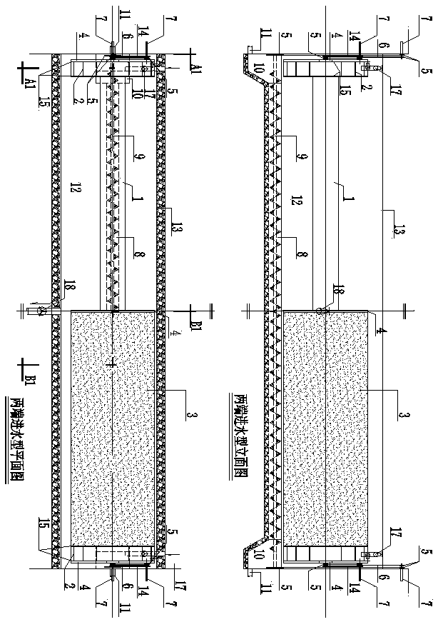
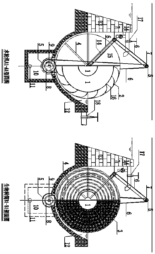
[0038] Specific embodiment one is water inlet type at both ends: details attached figure 1 And figure 2 . This type requires the construction of an overflow weir 13. The water flow enters the gravity turbine through the inlet pipe and valve 17 (if there is excess flow, it flows out through the bypass pipe on the inlet pipe and valve 17 or overflows through the top of the overflow weir). The water turbine and the biological drum are driven to rotate and enter the oxidation tank 12. The water bucket of the water turbine is composed of an impeller 2, two side plates 15 of the water turbine and a bottom plate 16 of the water bucket. The impeller 2 of the water turbine adopts a spiral blade with lower resistance. The connection between the impeller 2 and the water bucket bottom plate 16 can form a certain clamp. The angle can also be 90 degrees. The bucket bottom plate 16 and the two turbine side plates 15 also form an enclosed pontoon, and the bucket bottom plate 16 is also the c...
specific Embodiment 2
[0040] Specific embodiment two is the central water inlet type: details are attached image 3 And Figure 4 . Basically similar to the first embodiment, the difference is that the water turbine is set in the middle, and the number of water turbines is changed from two to one. The width of the water turbine may change due to changes in the amount of water. In addition, the inlet pipe and valve 17 and the outlet pipe and valve The position of 18 has also changed accordingly. The water flow enters from the middle and flows to both ends. It should also be pointed out that when the water intake cannot provide sufficient power, auxiliary power can be added, including speed monitoring sensor 23, variable frequency motor and reducer 24 and one-way (clutch) bearing 25. In this way, the minimum investment in power can be achieved and the aerobic treatment effect can be ensured. This equipment can also be used in the use environment of the non-oxidation tank 12. When used in this enviro...
specific Embodiment 3
[0041] Specific embodiment three is a radial water inlet type: details attached Figure 5 And Image 6 . The biggest feature of this model is that the body is both a hydraulic turbine and a biological drum. The pontoon shaft 1 of the biological drum is also the pontoon shaft 1 of the water turbine. The water turbine belongs to the propeller type water turbine. The length of the impeller 2 of the water turbine is the same as the length of the fuselage. Each impeller 2 is divided into two sections, one of which is rectangular and is fixed vertically on the outer wall of the pontoon. The spiral impeller 2 of each module is provided with several speed-adjusting flower baskets 20, and the angle of the movable impeller 2 is changed by adjusting the length of the speed-adjusting flower basket 20, so as to achieve the purpose of speed adjustment. The gap between the impeller 2 is provided with a lightweight packing 3, and the two ends of each module are provided with a packing bracke...
PUM
 Abstract
Description
Claims
Application Information
 - Generate Ideas
- Intellectual Property
- Life Sciences
- Materials
- Tech Scout
- Unparalleled Data Quality
- Higher Quality Content
- 60% Fewer Hallucinations
Browse by: Latest US Patents, China's latest patents, Technical Efficacy Thesaurus, Application Domain, Technology Topic, Popular Technical Reports.
© 2025 PatSnap. All rights reserved.Legal|Privacy policy|Modern Slavery Act Transparency Statement|Sitemap|About US| Contact US: help@patsnap.com