
A method for automatic vehicle tracking

A vehicle and tracking technology, applied in two-dimensional position/channel control and other directions to reduce transportation costs

Inactive Publication Date: 2018-02-02
SOUEAST
View PDF5 Cites 0 Cited by
  • Summary
  • Abstract
  • Description
  • Claims
  • Application Information

AI Technical Summary

Problems solved by technology

At present, there is no such device that can automatically identify the position of the vehicle in the lane, so as to control the steering and realize automatic tracking driving

Method used


Image

  • A method for automatic vehicle tracking
  • A method for automatic vehicle tracking

Examples


Embodiment Construction

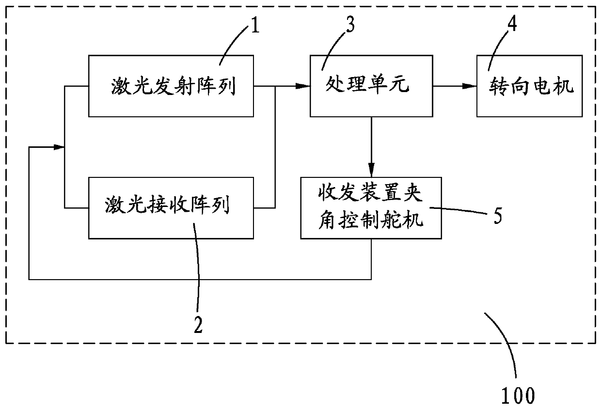
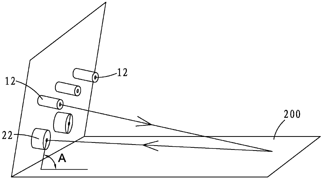
[0013] see figure 1 and figure 2 As shown, in the vehicle automatic tracking method of the present invention, a laser emitting array 1 and a laser receiving array 2 are arranged at the front end of the vehicle, and the laser emitting array 1 and the laser receiving array 2 are connected to a processing unit 3, and the processing unit 3 is connected to a steering motor 4 ; Then connect the laser emitting array 1 , laser receiving array 2 and processing unit 3 to a transceiver device angle control steering gear 5 .

[0014] Wherein, the number of laser tubes 12 in the laser emitting array 1 is determined by the width of the vehicle, so as to ensure that the distance between two adjacent beams does not exceed the width of the lane line. The laser tubes 12 in the laser emitting array 1 are grouped according to the number of receiving tubes 22 of the laser receiving array 2. If the laser receiving array 2 has four receiving tubes 22, the laser tubes 12 in the laser emitting array...


PUM


Abstract

The invention provides a vehicle automatic tracking method, comprising steps of arranging a laser emission array and a laser reception array in the front of the vehicle, connecting to a steering motor through a processing unit, and connecting the laser emission array, the laser reception array and the processing unit to an included angle control steering engine of a transmitter-receiver appliance. The tracking process comprises that: the laser reception array receives and outputs high-low level signals after the laser emission array emits modulated laser at different periods of time to a front ground to reflect according to the signals of the processing unit; the high-low level signal is received by the processing unit and converted to a deviation position of the vehicle; the turn angle of the steering motor is calculated and PWM signals are outputted to control the action of the steering motor; and the processing unit controls the included angle control steering engine of the transmitter-receiver appliance to regulate the emission angle of the laser emission array and the reception angle of the laser reception array. The invention can automatically identify the position of the vehicle on the road, realizes the automatic tracing driving and reduces the transport cost.

Description

technical field [0001] The invention relates to a method for automatic vehicle tracking, which can be used for express bus lines to realize unmanned driving. Background technique [0002] When the vehicle is driving on a road with lane markings, the driver needs to adjust the steering wheel in real time to ensure that the vehicle can drive along the lane. At present, there is no such device that can automatically recognize the position of the vehicle in the lane, thereby controlling the steering and realizing automatic tracking driving. Contents of the invention [0003] The technical problem to be solved by the present invention is to provide a vehicle automatic tracking method, which can automatically identify the position of the vehicle in the lane, thereby controlling the steering and realizing automatic tracking driving. [0004] The present invention is achieved as follows: a method for automatic vehicle tracking, in which a laser emitting array and a laser receivin...

Claims


Application Information

Patent Timeline
Patent Type & Authority Patents(China)
IPC IPC(8): G05D1/02
Inventor 林建锋施丽妮曾毅
Owner SOUEAST
Learn More