a composite floor
A technology for stacking slabs and beams, applied to slabs, building components, buildings, etc., can solve the problems of application impact, limited bearing capacity of prefabricated bottom plates, and increase the self-weight of laminated slabs, so as to reduce the amount of consumption, improve the thermal insulation ability, The effect of reducing self-weight
- Summary
- Abstract
- Description
- Claims
- Application Information
AI Technical Summary
Problems solved by technology
Method used
Image
Examples
Embodiment 1
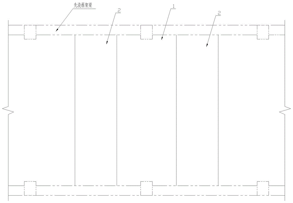
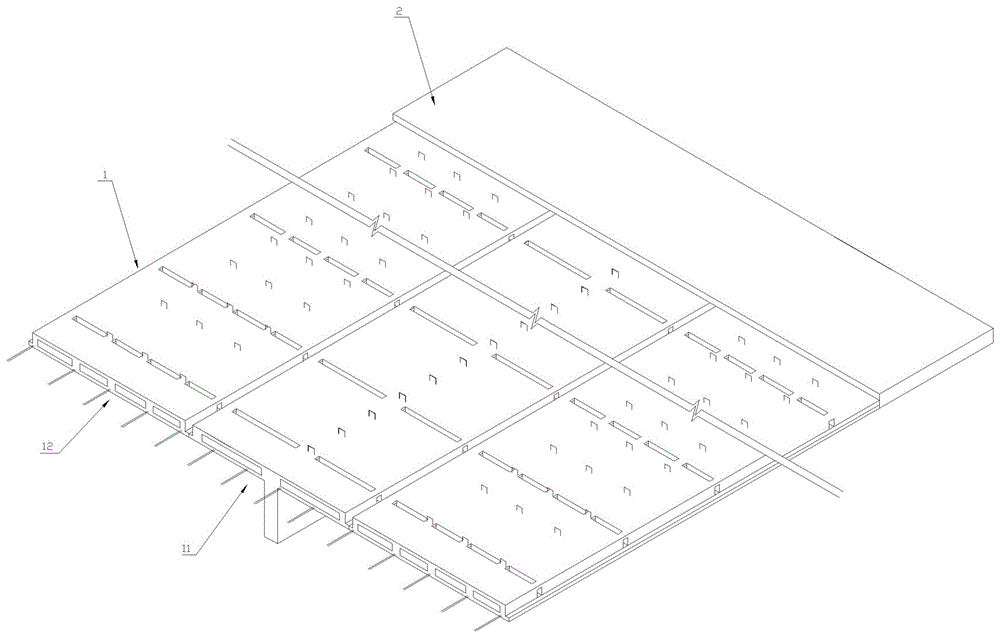
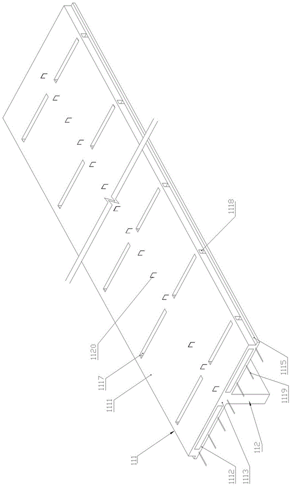
[0018] Embodiment one, such as Figure 2-4 As shown, this preferred embodiment discloses a laminated floor slab I, which includes a prefabricated layer I1 and a post-cast laminated layer I2 above it. The prefabricated layer I1 includes a T-beam slab I11 and a flat plate I12 equal in length to it. The flat plate I12 is arranged On both sides of T beam plate I11. The T beam plate I11 is a T-shaped integral prefabricated part of the horizontal roof I111 and the vertical beams 112 arranged below it along its length direction. The horizontal roof I111 is a frame structure surrounded by the upper panel I1111, the lower panel I1112 and the intersecting longitudinal ribs I1113 and transverse ribs I1114 between them, and the two sides of the lower panel I1112 have flanges along the length direction 1115, the longitudinal rib belt I1113 and the transverse rib belt I1114 are respectively arranged between the upper panel 1111 and the lower panel I1112 along the length direction and the w...
Embodiment 2
[0024] Embodiment two, such as Figure 5 As shown, this preferred embodiment discloses a laminated floor slab II, which differs from the first embodiment in that: in the horizontal roof of the T-beam slab II 101 and the flat plate II 102, the two sides in the width direction and the adjacent longitudinal ribs II 1011 The distance between them is smaller than the distance between two adjacent longitudinal ribbed strips II1011, and the other independent cavities except the independent cavities on both sides in the width direction are filled with corresponding filling blocks 1116; between two adjacent transverse ribbed strips II1012 In the area of each longitudinal rib belt, there is provided a longitudinal rib groove 1014 opening upward, and a longitudinal rib beam penetration hole II 1013 is provided in the longitudinal rib belt II 1011 along the longitudinal direction. Other structures and usages of this embodiment are the same as those in Embodiment 1.
Embodiment 3
[0025] Embodiment three, such as Image 6As shown, this preferred embodiment discloses a laminated floor slab III, which includes a prefabricated layer IIIA and a post-cast laminated layer IIIB above it. The prefabricated layer IIIA includes a T-beam slab IIIIA1 and a flat plate IIIA2 with the same length as the flat plate IIIA2. On both sides of T beam plate IIIA1.
[0026] The T beam plate IIIA1 is a T-shaped integral prefabricated part of the horizontal roof IIIA11 and the vertical beam IIIA12 arranged below it along its length direction.
[0027] The flat plate ⅢA2 includes the bottom panel ⅢA21 and the filling block ⅢA22. In order to ensure the effect of thermal insulation, the filling block ⅢA22 is made of light thermal insulation material; A transverse rib band IIIA23 is formed between two adjacent columns, and a longitudinal rib band IIIA24 is formed between two adjacent columns. There is a certain distance between the outer ends of the outermost two columns of the fi...
PUM
 Abstract
Description
Claims
Application Information
 - Generate Ideas
- Intellectual Property
- Life Sciences
- Materials
- Tech Scout
- Unparalleled Data Quality
- Higher Quality Content
- 60% Fewer Hallucinations
Browse by: Latest US Patents, China's latest patents, Technical Efficacy Thesaurus, Application Domain, Technology Topic, Popular Technical Reports.
© 2025 PatSnap. All rights reserved.Legal|Privacy policy|Modern Slavery Act Transparency Statement|Sitemap|About US| Contact US: help@patsnap.com


