
Sun array driven oscillating method for radar satellites in low-inclination orbits

A technology of solar array and low inclination, which is applied to the power supply system of aerospace vehicles, etc., can solve the problems of not being able to follow the sun-synchronous orbit solar array drive swing mode, and achieve the improvement of utilization efficiency and power supply capacity, and the drive swing mode is simple and optimized The effect of the area of ​​the cloth

Active Publication Date: 2017-05-03
SHANGHAI SATELLITE ENG INST
View PDF5 Cites 2 Cited by
  • Summary
  • Abstract
  • Description
  • Claims
  • Application Information

AI Technical Summary

Problems solved by technology

[0002] my country's remote sensing satellites mostly use sun-synchronous orbits, the sun's illumination angle is relatively stable, and the solar array drive swing mode is simple and fixed. For radar satellites, low-inclination orbits can be used, and the sun's illumination angle has a large range of variation, so it is impossible to continue to use sun-synchronous orbits. Orbiting Satellite Solar Array Driving Swing Mode

Method used


Image

  • Sun array driven oscillating method for radar satellites in low-inclination orbits
  • Sun array driven oscillating method for radar satellites in low-inclination orbits
  • Sun array driven oscillating method for radar satellites in low-inclination orbits

Examples


Embodiment Construction

[0043] The present invention will be described in detail below in conjunction with specific embodiments. The following examples will help those skilled in the art to further understand the present invention, but do not limit the present invention in any form. It should be noted that those skilled in the art can make several modifications and improvements without departing from the concept of the present invention. These all belong to the protection scope of the present invention.

[0044] In this embodiment, the solar array driving swing method of the low-inclination orbit radar satellite provided by the present invention includes the following steps:

[0045] Step 1: Determine the variation range of the angle β between the sun vector and the satellite orbital plane according to the orbital inclination i;

[0046] Step 2: Determine the installation surface and installation angle of the solar array according to the oblique flying state and configuration layout of the radar sa...


PUM


Abstract

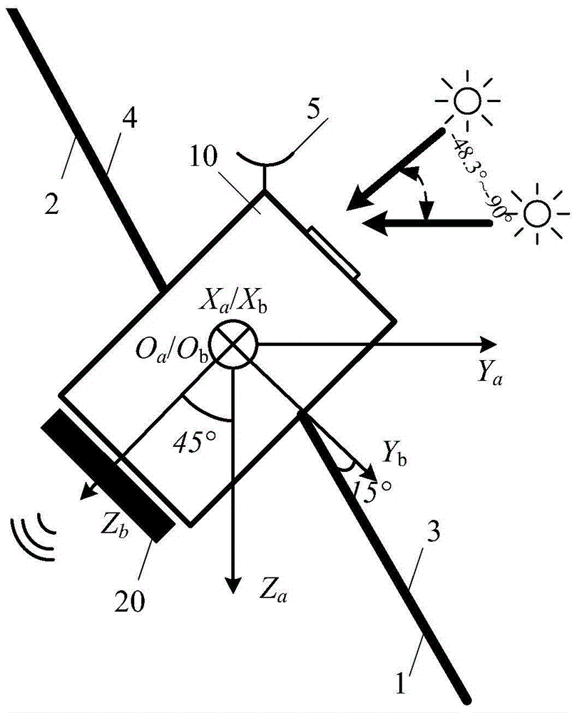
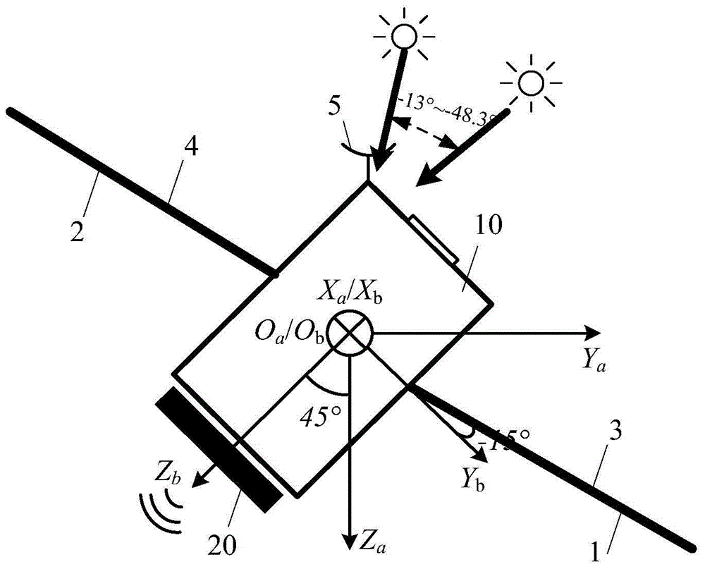
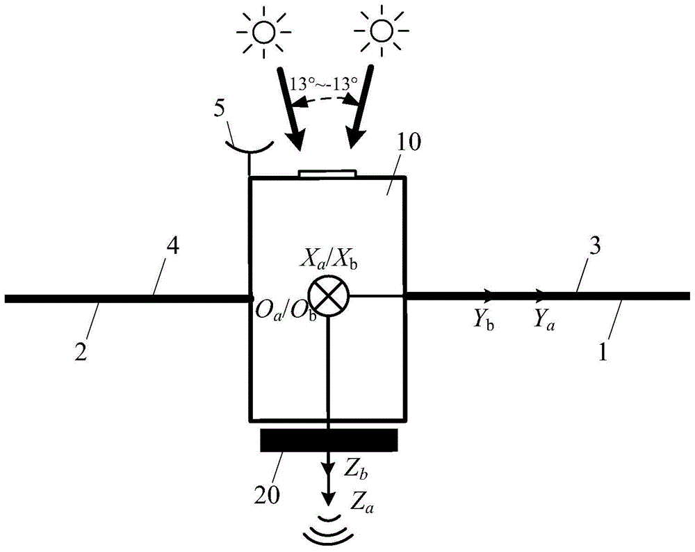
The invention provides a solar array driving swinging method for a low-dip-angle orbit radar satellite. The method comprises the following steps of firstly, determining the variation range of the included angle beta between the solar vector and a satellite orbit plane according to the dip angle i of an orbit; secondly, determining an installation plane and an installation angle of a solar array according to the oblique flying state and the configuration layout of the radar satellite; thirdly, determining the swinging angle of the solar array according to the satellite flying attitude and the included angle beta between the solar vector and the satellite orbit plane, and then determining the driving state of the solar array. According to the solar array driving swinging method, a satellite has five in-orbit states totally according to the angle beta variation condition of the satellite and has the three flying attitudes including 45-degree on left side viewing, level flight and 45-degree on right side viewing. According to the tip angle of the orbit, the solar array driving swinging state of the radar satellite is reasonably set, and it is ensured that the illumination angle within the whole service life of the satellite is larger than 50 degrees.

Description

technical field [0001] The invention relates to the overall design of satellites, in particular to a method for driving and swinging a solar array of a low-inclination orbit radar satellite. Background technique [0002] my country's remote sensing satellites mostly use sun-synchronous orbits, the sun's illumination angle is relatively stable, and the solar array drive swing mode is simple and fixed. For radar satellites, low-inclination orbits can be used, and the sun's illumination angle has a large range of variation, so it is impossible to continue to use sun-synchronous orbits. Orbiting satellite solar array drive swing mode. [0003] In order to ensure the energy supply of low-inclination orbit satellites throughout the life cycle, and to reduce the area of ​​the solar array, it is necessary to reasonably set the driving and swinging mode of the solar array according to the solar illumination angle on the orbit. This method should be as simple as possible and easy acco...

Claims


Application Information

Patent Timeline
Patent Type & Authority Patents(China)
IPC IPC(8): B64G1/44
Inventor 陆晴孙永岩万向成陈筠力
Owner SHANGHAI SATELLITE ENG INST
Learn More