Vacuum suction cup type mechanical paw

A technology of vacuum suction cups and robotic grippers, applied in the field of robotic grippers, can solve the problems of complex structure and poor practicability, and achieve the effects of good wear resistance, simple structure and stable work

Inactive Publication Date: 2015-11-11
NANTONG DILONG KNITTING GARMENT
View PDF0 Cites 0 Cited by
  • Summary
  • Abstract
  • Description
  • Claims
  • Application Information

AI Technical Summary

Problems solved by technology

Therefore, at present, many mechanical claws have complex structures and poor practicability.

Method used


Image

  • Vacuum suction cup type mechanical paw

Examples


Embodiment Construction

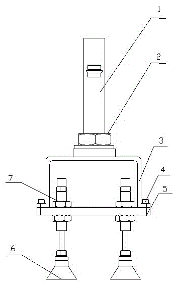
[0013] Such as figure 1 As shown, the present invention discloses a vacuum suction cup mechanical gripper, comprising a handle 1, a support plate 3 connected to the handle 1, a connection plate 5 connected to the lower part of the support plate 3, and a pair of uprights 7 arranged on the connection plate 5 , the vacuum sucker 6 at the bottom of the column 7; the handle 1 is connected to the middle part of the upper plane of the support plate 3 through a nut, the support plate 3 is integrally formed with a horizontal plate and two vertical plates, and the bottom of the two vertical plates extends vertically outwards respectively The fixed end face is connected to the connecting plate 5 by screws; the connecting plate 5 has two identical through holes for a pair of columns 7 to be inserted into; There are threads on the surface, which are plugged and matched with the through holes on the connecting plate, and are respectively fixed with nuts on the upper and lower surfaces of th...


PUM


Abstract

The invention relates to a vacuum suction cup type mechanical paw which comprises a handle, a supporting plate connected with the handle, a connection plate connected to the lower portion of the supporting plate, a pair of stand columns arranged on the connection plate and vacuum suction cups at the bottom ends of the stand columns. The handle is connected to the middle of an upper plane of the supporting plate through a nut. The supporting plate is integrally formed by a horizontal plate and two vertical plates. The lower portions of the two vertical plates extend outwards and perpendicularly to form fixing end faces respectively and connected to the connection plate. The pair of stand columns is formed by connecting two columnar structures of different diameters, matched with through holes in the connection plate in an inserting manner and fixed to the upper surface and the lower surface of the connection plate through nuts. The vacuum suction cup type mechanical paw has the beneficial effects that the vacuum suction cup type mechanical paw is simple in structure and more stable to work by the adoption of the two suction cups; the position where the handle is connected with the supporting plate through the nut is provided with a spacer, and the functions that the pressure on unit area is lowered, and the surfaces of connected parts are protected against damage are achieved; and the vacuum suction cups are made of polyurethane, and abrasion resistance is good.

Description

technical field [0001] The invention relates to a mechanical claw, in particular to a vacuum suction cup type mechanical claw. Background technique [0002] Robotic grippers can realize robotic parts that function like human hands. The robot gripper is a component used to hold workpieces or tools, and is one of the important actuators. The structure of the gripper for gripping heavy objects is relatively complicated, but for grabbing lighter materials, the structure of the gripper does not need to be too complicated. Therefore, at present, many mechanical grippers have complex structures and poor practicability. Contents of the invention [0003] The technical problem to be solved by the present invention is to provide a vacuum sucker type mechanical gripper with simple structure and strong practicability. [0004] In order to solve the above technical problems, the technical solution of the present invention is: a vacuum suction cup type mechanical gripper, its innovat...

Claims


Application Information

Patent Timeline
Patent Type & Authority Applications(China)
IPC IPC(8): B25J15/06
Inventor 施辉
Owner NANTONG DILONG KNITTING GARMENT
Why Eureka
Try Eureka