wheel suspension for vehicles

A technology of wheel suspension and wheel frame, which is applied in the field of wheel suspension for vehicles, and can solve the problems of increasing the weight of wheel suspension and occupying construction space, etc.

Active Publication Date: 2019-04-19
FORD GLOBAL TECH LLC
View PDF8 Cites 0 Cited by
  • Summary
  • Abstract
  • Description
  • Claims
  • Application Information

AI Technical Summary

Problems solved by technology

However, both known possibilities have the disadvantage that they take up a certain construction space and, due to the number of necessary components, increase the weight of the wheel suspension and are cost-intensive

Method used


Image

  • wheel suspension for vehicles
  • wheel suspension for vehicles
  • wheel suspension for vehicles

Examples


Embodiment Construction

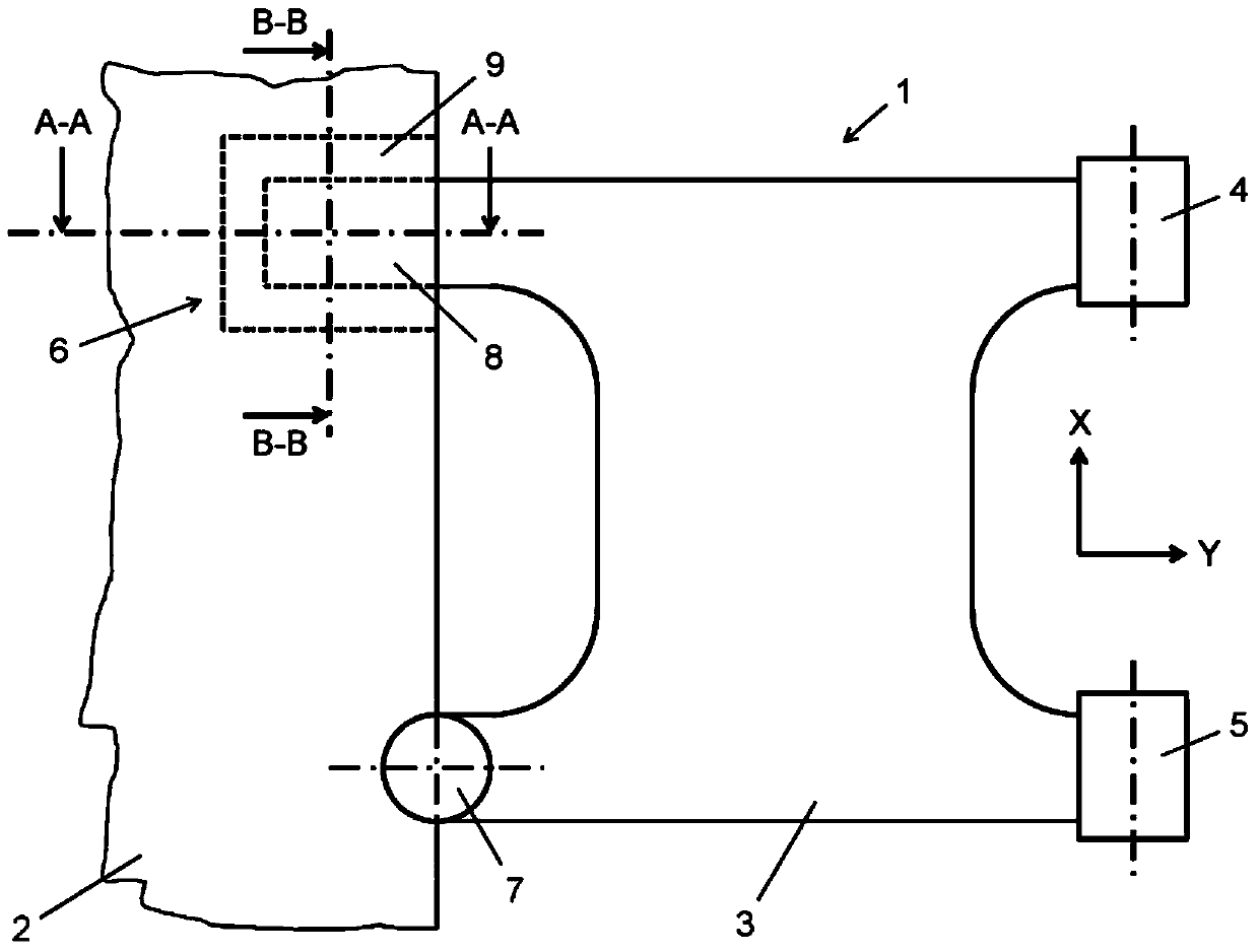
[0022] figure 1 A plan view of a wheel suspension 1 according to the invention for a vehicle, in particular for a motor vehicle, is shown. exist figure 1 The spatial directions X and Y shown in represent a direction parallel to the longitudinal axis of the vehicle (direction X) and a direction parallel to the transverse axis of the vehicle (direction Y).

[0023] as from figure 1 As can be seen, the wheel suspension 1 comprises a wheel carrier 2 which rotatably supports a wheel (not shown). The wheel carrier 2 is pivotally mounted on a torsionally rigid transverse control arm 3 which is in turn pivotally mounted on the vehicle superstructure (not shown) or a subframe connected to the vehicle superstructure (also not shown) on. For this purpose, the transverse control arm 3 has two control arm bearings 4 (front control arm bearing on the superstructure side in the direction of vehicle travel) and 5 (rear control arm bearing on the superstructure side in the direction of veh...


PUM


Abstract

The invention relates to a wheel suspension for a vehicle, comprising a wheel carrier (2) rotatably supporting the wheel and pivotally mounted on a torsionally rigid transverse control arm (3), Said lateral control arm (3) is provided with two control arm bearings (4, 5) for pivotal mounting on the vehicle superstructure and with two control arm bearings (4, 5) for pivotal mounting on the wheel carrier (2). Two control arms (6, 7) on the wheel carrier side, wherein the front control arm bearing (6) on the wheel carrier side in the direction of travel of the vehicle is formed as a movable bearing (6), and the movable bearing ( 6) The force can be transmitted in one of three spatial directions (X, Y, Z), wherein the spatial direction in which the movable bearing (6) can transmit the force corresponds to the direction parallel to the vertical axis of the vehicle.

Description

technical field [0001] The present invention relates to wheel suspensions for vehicles, in particular motor vehicles, and in particular to wheel suspensions comprising a wheel carrier rotatably supporting a wheel and pivotally mounted on a torsionally rigid On the transverse control arm with two control arm bearings on the superstructure side for pivotally mounted on the vehicle superstructure or on a subframe connected to the vehicle superstructure, and with Two control arm bearings on the wheel frame side pivotally mounted on the wheel frame. Background technique [0002] Such wheel suspensions are generally known. Conventionally, the rear control arm bearing on the wheel carrier side in the direction of travel of the vehicle is formed, for example, as a ball joint, which can transmit forces in all three spatial directions. The front control arm bearing on the wheel carrier side in the direction of vehicle travel is conventionally arranged such that it is in a direction ...

Claims


Application Information

Patent Timeline
Patent Type & Authority Patents(China)
IPC IPC(8): B60G3/06
CPCB60G7/001B60G7/005B60G7/02B60G2204/416B60G2206/121
Inventor 拉尔夫·辛茨恩弗雷德里克·彼得·沃尔夫-蒙海姆
Owner FORD GLOBAL TECH LLC
Why Eureka
Try Eureka