Rectilinear motion linear module and position control servo system provided with module

A linear module, linear motion technology, applied in the field of automation, can solve the problems of ball screw implementation length and dimension limitation, difficulty in high-speed operation of the device, difficult ball screw processing, etc., to achieve low cost, high speed, and short response time. Effect

Inactive Publication Date: 2015-10-28
杨光
View PDF7 Cites 14 Cited by
  • Summary
  • Abstract
  • Description
  • Claims
  • Application Information

AI Technical Summary

Problems solved by technology

Although the linear module is widely used and has good performance, it also has some obvious disadvantages: the high-precision ball screw is difficult to process and the cost is high, which limits the length and size of the ball screw. Difficulties with high-speed operation of the device

Method used


Image

  • Rectilinear motion linear module and position control servo system provided with module
  • Rectilinear motion linear module and position control servo system provided with module
  • Rectilinear motion linear module and position control servo system provided with module

Examples


specific Embodiment 1

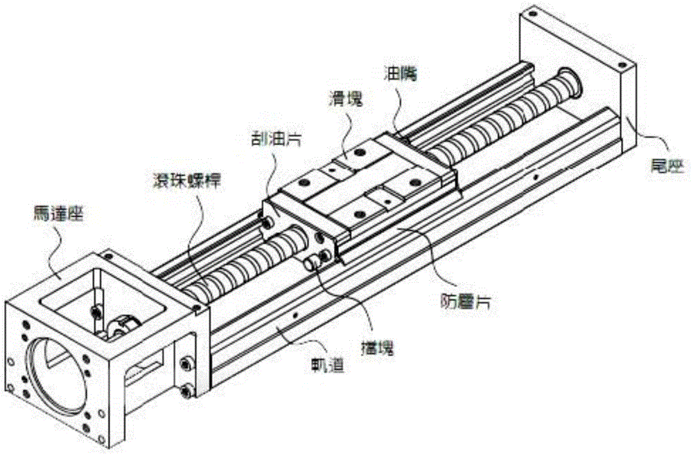
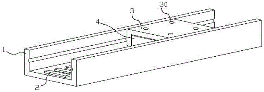
[0033] A linear motion linear module, including a channel-shaped steel body 1 formed by processing pure iron or low-carbon steel, a mover seat 3 that reciprocates on the channel-shaped steel body 1, and a mover seat 3 that cooperates with each other to drive the mover seat 3 moving mover block 4 and stator block 2;

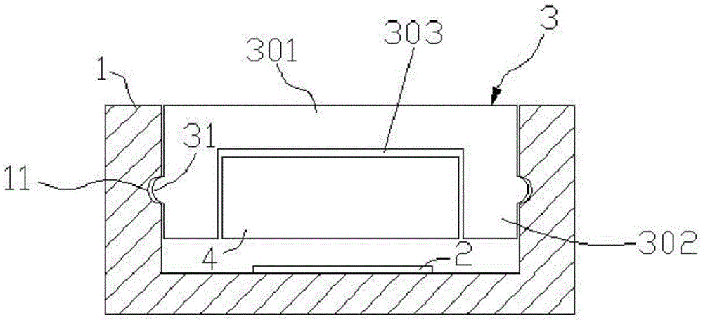
[0034] A group of linear guide grooves 11 are symmetrically arranged on the inner wall of the channel-shaped steel body 1;

[0035] The mover seat 3 is placed in the groove of the channel-shaped steel body 1, and the surface on both sides is provided with a guide structure matching the guide groove 11 of the channel-shaped steel body 1, and the guide structure is convexly arranged on the The surface of the mover seat 3, the protrusion or convex line 31 embedded and sliding along the guide groove 11 of the channel steel body 1; the surface of the guide groove 11 or protrusion adopts laser quenching or other forms of surface hardening and wear resistance deal with....

specific Embodiment 2

[0042] The difference from the above-mentioned specific embodiment 1 is that the inner side wall of the channel-shaped steel body 1 is provided with a straight-line guide rail 12, and the mover seat 3 is placed in the groove of the channel-shaped steel body 1. The surface on both sides is provided with a guiding structure matching the guiding convex rail 12 of the channel-shaped steel body 1. a groove 32 into which the rail 12 fits and slides;

[0043] The guide rail 12 of the channel-shaped steel body 1 and the groove 32 of the mover seat 3 are in a "U" shape or a "V" shape or other combined shapes that cooperate with each other.

specific Embodiment 3

[0045] The difference from the above-mentioned specific embodiment 1 is that balls 5 are arranged between the guide groove 11 of the channel-shaped steel body 1 and the protruding line 31 of the mover seat 3, and single or multiple rows of balls 5 and the guide groove are used. 11, the rolling contact is used to reduce the frictional force between the convex strip 31 and the guide groove 11.


PUM


Abstract

The invention provides a rectilinear motion linear module, and aims to solve the operation accuracy, the speed, the module size, the cost and other problems in the linear module application field. According to the technical scheme of the invention, the rectilinear motion linear module comprises a trough type steel body, a mover base capable of conducting the reciprocating motion on the trough type steel body, a mover block and a stator block. The mover block and the stator block cooperate with each other to drive the mover base to move. The inner sidewall of the trough type steel body is provided with a guide groove or a guide bump orbit along the linear direction. The mover base is arranged in the trough of the trough type steel body. The surfaces of the two sides of the mover base are provided with a guiding structure matched with the guide groove/guide bump orbit of the trough type steel body. The mover blocks comprise multi-phase coreless coil windings or multi-phase coil windings with high-permeability cores, and are arranged below the mover base. The mover blocks are connected with a motor driver to be controlled by the motor driver. The stator blocks are in the form of permanent magnets and are arranged alternately along the inner bottom surface of the trough of the trough type steel body or along the extending direction of the guide bump orbit. Gaps are reserved between the mover blocks and the stator blocks.

Description

technical field [0001] The invention relates to the technical field of automation, in particular to a linear motion linear module and a position control servo system using the module. Background technique [0002] A large number of linear modules are currently used in the automation industry, such as figure 1 As shown, the commonly used KK linear module consists of a motor, a ball screw, a guide rail and a nut mover seat. The motor drives the ball screw to rotate, and drives the nut mover seat on the screw to make a reciprocating straight line along the guide rail. sports. Although the linear module is widely used and has good performance, it also has some obvious disadvantages: the high-precision ball screw is difficult to process and the cost is high, which limits the length and size of the ball screw. There is difficulty in running the device at high speed. Contents of the invention [0003] In view of the problems mentioned in the background technology, the present ...

Claims


Application Information

Patent Timeline
Patent Type & Authority Applications(China)
IPC IPC(8): H02K33/18
Inventor 曲鲁杰杨光
Owner 杨光
Why Eureka
Try Eureka