


Quick Research
Generate reliable direction feasibility study reports for your R&D in just a few steps.

Technical Q&A
Discover and master advanced knowledge NOW. Basics, ideas, possibilities, all at once.

Find Solutions
As an expert in R&D theories, this can generate solutions to your technical problems instantly.

Evaluate Feasibility
Analyze your overall solution with one click, know your potential R&D risks in advance.

Monitor Landscape
Get weekly tech updates, stay abreast of the latest tech innovations and key insights.
A method of finding a feature using a machine tool
A machine tool, application and installation technology, applied in the field of scanning measurement tools to identify objects, can solve the problems of long measurement time and slow measurement process
- Summary
- Abstract
- Description
- Claims
- Application Information
AI Technical Summary
Problems solved by technology
Method used
Image

Examples
Embodiment Construction
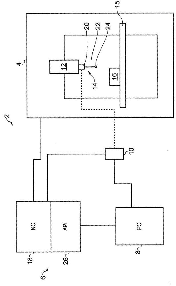
[0048] refer to figure 1 , shows a machine tool installation 2 comprising a machine tool 4 , a controller 6 , a PC 8 and a transmitter / receiver interface 10 . The machine tool 4 includes a motor (not shown) for moving a spindle 12 holding a dummy probe 14 relative to a workpiece 16 positioned on a table 15 . The position of the spindle 12 (and thus the analog probe 14) is precisely measured in a known manner using an encoder or the like. This measurement provides spindle position data defined in the machine coordinate system (x, y, z). A numerical controller (NC) 18 (which is part of the controller 6 ) controls the x, y, z movement of the spindle 12 in the working area of the machine tool and also receives data on the position of said spindle.
[0049]As will be appreciated, in alternative embodiments, relative motion in any or all of the x, y, z dimensions may be provided by motion of the table 15 relative to the spindle. Furthermore, relative rotational motion of simula...
PUM
 Abstract
Description
Claims
Application Information
 - R&D Engineer
- R&D Manager
- IP Professional
- Industry Leading Data Capabilities
- Powerful AI technology
- Patent DNA Extraction
Browse by: Latest US Patents, China's latest patents, Technical Efficacy Thesaurus, Application Domain, Technology Topic, Popular Technical Reports.
© 2024 PatSnap. All rights reserved.Legal|Privacy policy|Modern Slavery Act Transparency Statement|Sitemap|About US| Contact US: help@patsnap.com