Method for producing a motor vehicle lock by targeted oblique punching of the locking faces of a locking part

A technology for motor vehicles and locking surfaces, which is applied in the application of locks, building locks, vehicle locks, etc., can solve problems such as troubles, and achieve the effect of reducing noise load

Active Publication Date: 2017-06-09
KIEKERT AG
View PDF6 Cites 0 Cited by
  • Summary
  • Abstract
  • Description
  • Claims
  • Application Information

AI Technical Summary

Problems solved by technology

This can be cumbersome or difficult to achieve, especially if the grooves on the locking part have to be produced at different angles of around 90° each

Method used


Image

  • Method for producing a motor vehicle lock by targeted oblique punching of the locking faces of a locking part
  • Method for producing a motor vehicle lock by targeted oblique punching of the locking faces of a locking part
  • Method for producing a motor vehicle lock by targeted oblique punching of the locking faces of a locking part

Examples


Embodiment Construction

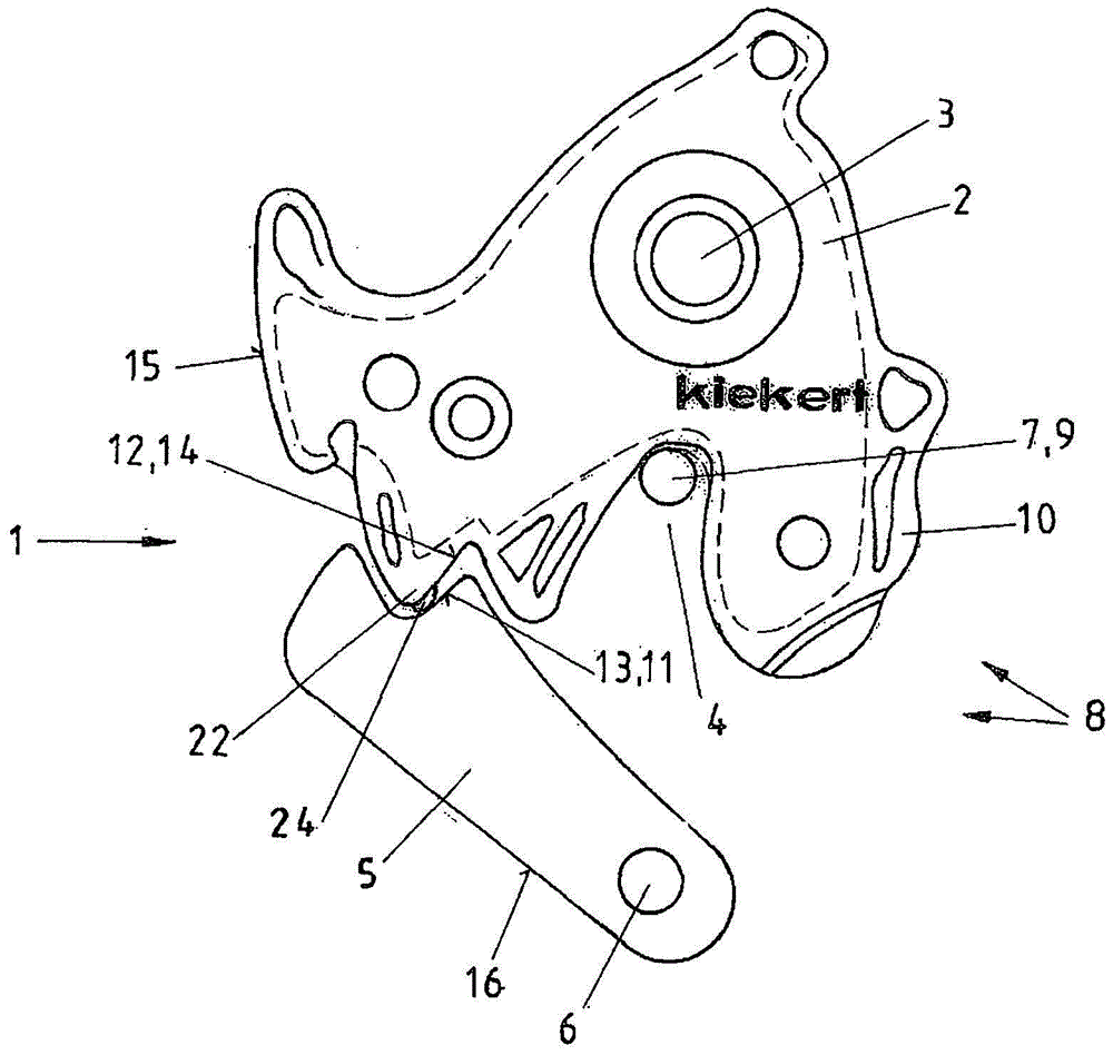
[0023] figure 1 A plan view of a motor vehicle lock 1 with two locking parts 30 , 31 is shown, wherein a rotary locking fork 2 pivotable on an axis 3 is secured by a pawl 5 . A locking bow 7 with a locking bow leg 9 is located in the receptacle 4 of the rotary locking fork 2 .

[0024] The rotary locking fork 2 is secured by the pawl 5 which is pivotable about the pawl axis 6 , that is to say, the motor vehicle lock 1 can only be reactivated if the pawl 5 has been swung away beforehand (this is achieved by a door handle not shown here). Open.

[0025] In order to be able to securely surround the locking bow leg 9 of the locking bow 7 , the rotary locking fork 2 has a correspondingly designed receptacle 4 . It is considered here that the locking bow 7 with the locking bow leg 9 is assigned to the chassis of the motor vehicle, while the locking device 8 with the rotary locking fork 2 and the pawl 5 is assigned to the motor vehicle door.

[0026] It is not emphasized in partic...


PUM


Abstract

The invention relates to a motor vehicle lock. In order to minimize the noise that occurs between the individual locking parts (30, 31) of the motor vehicle lock (1), it is provided that during the manufacturing process on the locking parts (30, 31) or on their locking surfaces (12, 13) flutes that extend at an angle relative to each other are produced. The resulting flutes ( 17 , 18 , 19 ) then have only a small overlap ( 25 ), which leads to a significant reduction in sliding friction and noise load.

Description

technical field [0001] The present invention relates to a method for the manufacture and installation of locking components (i.e. locking pawl and rotary yoke) of a motor vehicle lock, as well as a locking bow (or lock catch) having at least Locking bow leg, wherein, punch out the locking pawl and the rotary locking fork that have vertical or approximately vertical edge (or be called side) and corresponding locking surface that is subjected to friction during opening and closing process and carry out The mounting is such that the punched and cut surface contours extend at an angle relative to each other in the region of the locking surface. The invention also relates to a motor vehicle lock having a locking part (ie a rotary locking fork with a receptacle for the lock bow) and a locking part (ie locking pawl) that fixes the rotary locking fork in the locked state, the two locking The part is stamped or cut from sheet metal, in particular sheet metal, and has a surface structu...

Claims


Application Information

Patent Timeline
Patent Type & Authority Patents(China)
IPC IPC(8): E05B85/26E05B77/40B21D28/36
CPCE05B85/26E05B17/0004B21D28/16Y10T29/49828Y10T292/1075E05B85/243E05B79/10
Inventor T·班德尔W·波利T·瓦尔德曼
Owner KIEKERT AG
Why Eureka
Try Eureka