
A device for improving channel isolation of radio frequency switch matrix

A radio frequency switch matrix and isolation technology, applied in the microwave field, can solve the problems of limited number of switches, poor maintainability, and poor versatility, and achieve the effects of easy maintenance, easy operation, and easy integration

Active Publication Date: 2018-07-24
THE 41ST INST OF CHINA ELECTRONICS TECH GRP
View PDF4 Cites 0 Cited by
  • Summary
  • Abstract
  • Description
  • Claims
  • Application Information

AI Technical Summary

Problems solved by technology

[0004] The traditional switch matrix channel is only composed of matrix array units, and the corresponding row isolation array units and column isolation array units are not designed. There is no necessary isolation circuit in the middle, and there is crosstalk between rows and rows, columns and columns, and rows and columns, resulting in low isolation indicators between channels.
[0005] The hardware circuit layout of the traditional switch matrix array unit adopts the single-sided layout of the printed board. The number of switches integrated in a unit area is limited, and it cannot meet the testing requirements of the multi-channel automatic test system in the limited space. Surface layout integration is not high
[0006] The external control unit and matrix array unit of the traditional RF switch matrix module are implemented on the same circuit board. This method is relatively compact in structure, but for modular instruments, it does not reflect the concept of unit design, and the maintainability is also poor. Not strong, if a part fails, it is not easy to troubleshoot
[0007] All kinds of traditional RF switch matrix modules are based on specific bus interface standards. In the process of building an automatic test system, specific bus control equipment is required to work. If users want to use this module, they can only select specific bus interface equipment. Sex is not strong

Method used


Image

  • A device for improving channel isolation of radio frequency switch matrix
  • A device for improving channel isolation of radio frequency switch matrix
  • A device for improving channel isolation of radio frequency switch matrix

Examples


Embodiment Construction

[0044] The following will clearly and completely describe the technical solutions in the embodiments of the present invention with reference to the accompanying drawings in the embodiments of the present invention. Obviously, the described embodiments are only some, not all, embodiments of the present invention. Based on the embodiments of the present invention, all other embodiments obtained by persons of ordinary skill in the art without making creative efforts belong to the protection scope of the present invention.

[0045] The traditional RF switch matrix device has the following disadvantages: 1) The channel isolation is not high; 2) The number of switches arranged per unit area is limited, which cannot meet the requirements of multi-channel testing. The present invention combines the characteristics of the miniaturization of the test device, increases the channel isolation of the radio frequency switch matrix device by increasing the isolation circuit and the optimizatio...


PUM


Abstract

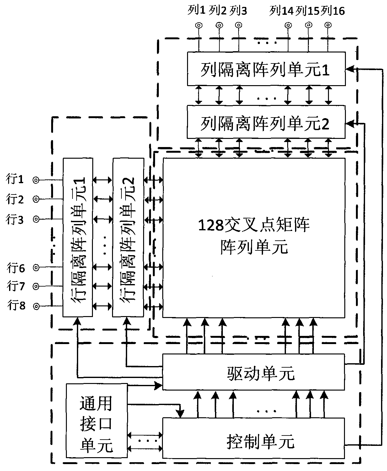
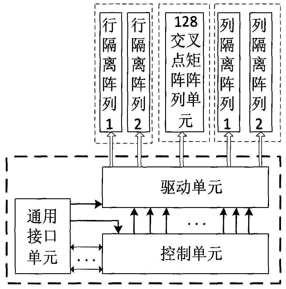
The present invention proposes a device for improving channel isolation of a radio frequency switch matrix, which is characterized in that it includes: a general interface unit, a control unit, a drive unit, a cross-point matrix array unit, a row isolation array unit 1, a row isolation array unit 2, Column isolation array unit 1, column isolation array unit 2; the main control computer sends the channel control code to the control unit through the general interface unit, the control unit decodes the address and sends it to the drive unit, and the drive unit receives the code according to the different codes sent. Switching on or off the switches in the cross-point matrix array unit and row isolation array unit 1, row isolation array unit 2, column isolation array unit 1, and column isolation array unit 2 realizes the control of the corresponding radio frequency switch matrix channel. The invention is easy to operate and has strong versatility; the index of radio frequency path isolation is high; it is convenient for maintenance; the whole device has high internal integration and small volume, and is convenient for the integration of an automatic test system.

Description

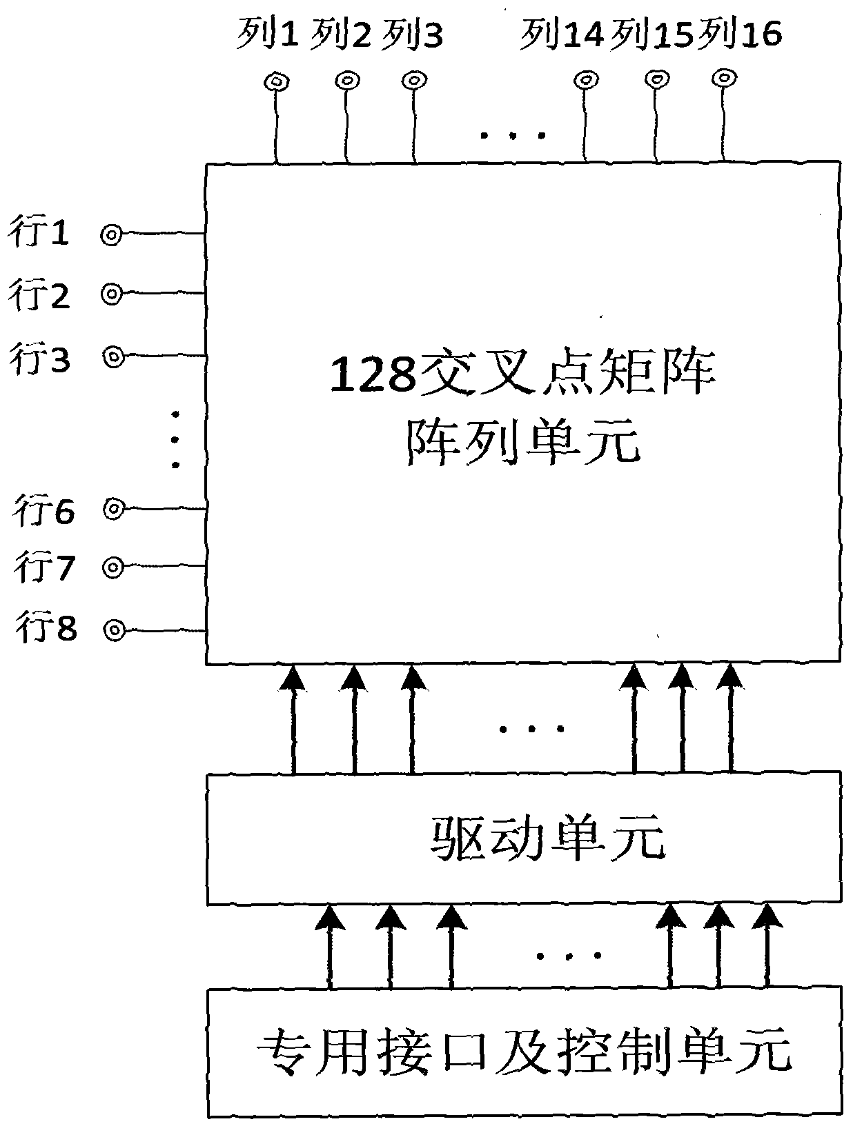
technical field [0001] The invention relates to the microwave field, in particular to a device for improving channel isolation of a radio frequency switch matrix. Background technique [0002] The traditional RF switch matrix device does not design the corresponding channel isolation circuit, the isolation between channels is not high, and it is easy to cause interference between channels during multi-channel testing, which affects the test results and cannot meet the test requirements. [0003] Traditional 128 cross-point RF switch matrix modules such as figure 1 As shown, it is mainly composed of 128 cross-point matrix array units, drive units, dedicated interfaces and control units. The main control computer sends different parameters through a dedicated bus to control each radio frequency switch matrix channel. [0004] The traditional switch matrix channel is only composed of matrix array units, and the corresponding row isolation array units and column isolation arra...

Claims


Application Information

Patent Timeline
Patent Type & Authority Patents(China)
IPC IPC(8): H04B1/525H03K17/56H03K17/76
Inventor 刘军智曹宁
Owner THE 41ST INST OF CHINA ELECTRONICS TECH GRP
Learn More