The base of the combined electrical box

A combined, electrical technology, applied in electrical components, substation/switch layout details, etc., can solve the problems of complex shape and structure, scrapping, high cost of mold opening, achieve reasonable connection structure design, ensure overall bearing capacity, mold opening cost reduction effect

Inactive Publication Date: 2018-06-19
NINGBO HUAYUAN FRP ELECTRICAL APPLIANCE MFR
View PDF4 Cites 0 Cited by
  • Summary
  • Abstract
  • Description
  • Claims
  • Application Information

AI Technical Summary

Problems solved by technology

[0002] The base of the electrical box in the prior art is generally a glass fiber reinforced plastic structure or an integral injection molded plastic structure that is split in two halves or integrally molded. Regardless of whether it is a two-half type or an integral type, there are complex shapes and structures. A series of problems such as high cost, high molding scrap rate, and low yield
Moreover, once a part of the integral type is damaged, the whole is completely scrapped.
In the prior art, there are also split bases, but the strength requirements of the connectors of each part of the split base are very high, and sheet metal connectors must be used, such as right-angled two-way sheet metal connectors or three-way XYZ three-way connectors. Connect the various parts into an integral base through sheet metal parts, which will inevitably increase the overall cost of the base, and the installation process of the sheet metal connectors is very cumbersome, time-consuming and laborious; moreover, the split base is also composed of parts with different structures , each part still needs to open a set of molds separately, and the cost of mold opening is still high

Method used


Image

  • The base of the combined electrical box
  • The base of the combined electrical box

Examples


Embodiment Construction

[0016] The present invention will be further described below with reference to the accompanying drawings and specific embodiments.

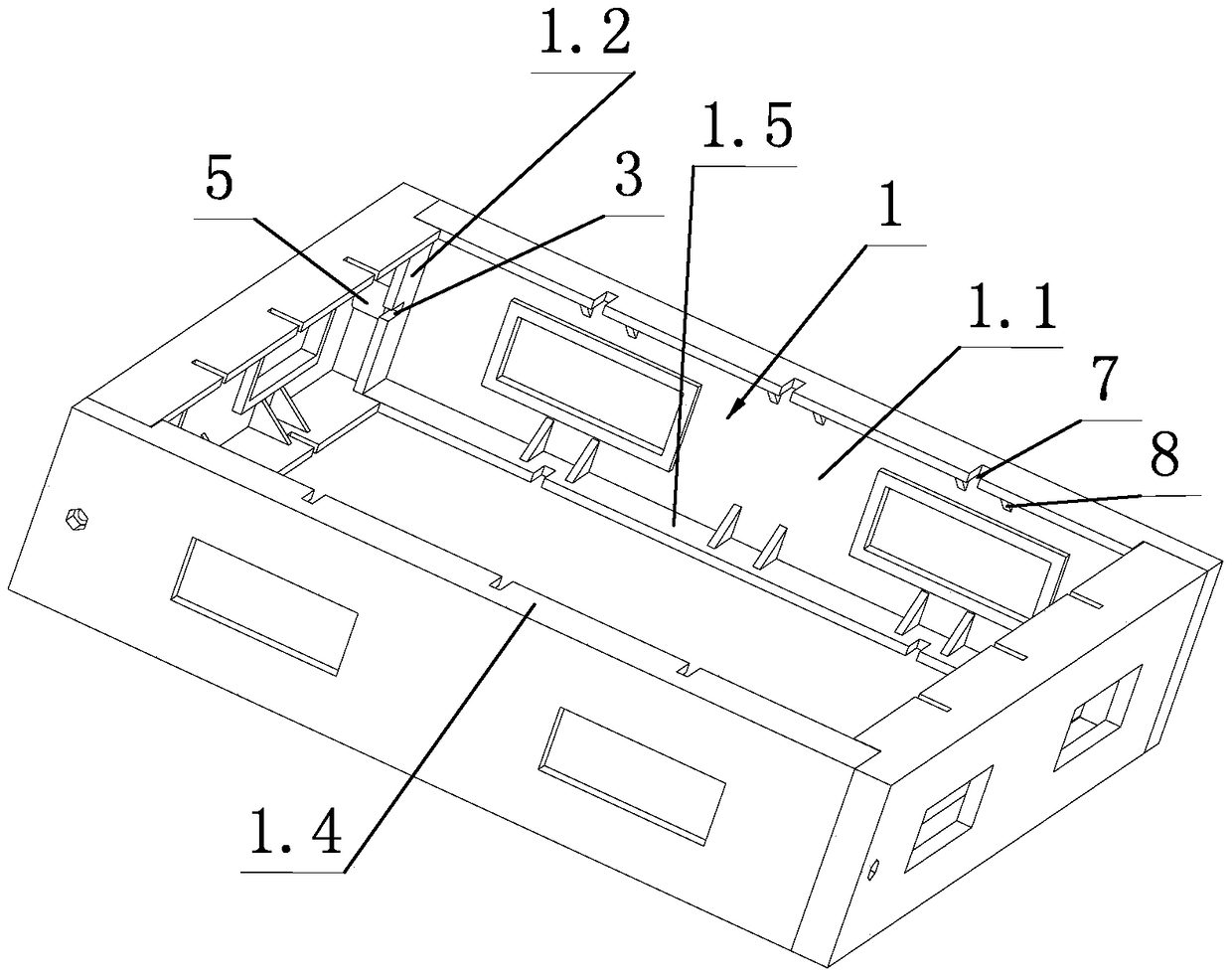
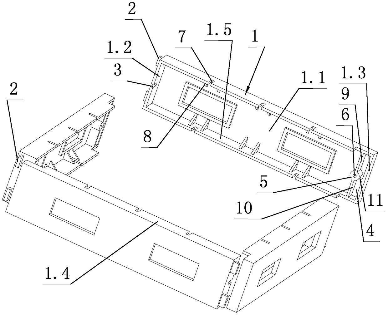
[0017] like figure 1 , figure 2 As shown, the base of the combined electrical box of the present invention includes four side connecting boards 1 with identical structures.

[0018] Each side connecting plate 1 includes a main panel 1.1, the head end of the main panel 1.1 is fixed with a head side flange 1.2, the rear end of the main panel 1.1 is fixed with a tail side flange 1.3, and the upper side of the main panel 1.1 is fixed with an upper side flip. Side 1.4, the lower side of the main panel 1.1 is fixed with a lower side flange 1.5. The head flanging 1.2, the upper flanging 1.4, the tail flanging 1.3 and the lower flanging 1.5 are connected in sequence, in other words, the upper ends of the head flanging 1.2 and the tail flanging 1.3 are respectively connected with the upper flanging 1.4 The lower ends of the head flange 1.2 and the tai...


PUM


Abstract

The invention discloses a base of a combined electric box body, which comprises four identical side connecting plates (1); each side connecting plate (1) comprises a main panel (1.1) and a first side flange (1.2) , the first side flange (1.2) is provided with a limiting protrusion (2), the first side flange (1.2) is provided with a first screw groove (3), and the back of the main panel (1.1) is provided with a limiting slot (4) and threaded holes (6); the four side connecting plates (1) are connected end to end to form a closed box, and the limit protrusion (2) at the head end of each side connecting plate (1) is inserted into the end of the previous side connecting plate (1) and the head end of each side connecting plate (1) passes through the first screw slot (3) of the side connecting plate (1) and is screwed into the previous side connecting plate (1) ) screw in the threaded hole (6) at the tail side is fixed to the tail side of the previous side connecting plate (1). The base has the advantages of simple structure, convenient assembly, low mold opening cost and good strength.

Description

technical field [0001] The invention relates to a base of an electrical box, in particular to a base of a combined cable branch box or power branch box. Background technique [0002] The base of the electrical box in the prior art is generally a glass fiber reinforced plastic structure or an integral injection-molded plastic structure that is assembled in two halves or integrally molded. A series of problems such as high cost, high scrap rate of molding and low yield. Moreover, once the monolith is damaged in part, the whole is completely scrapped. In the prior art, there are also split-type bases, but the strength requirements of the connecting parts of each part of the split-type base are very high, and sheet metal connecting parts must be used, such as right-angle two-way sheet metal connecting parts or three-way connecting parts in three directions of XYZ. The various parts are connected into a whole base through sheet metal parts, which will inevitably increase the ov...

Claims


Application Information

Patent Timeline
Patent Type & Authority Patents(China)
IPC IPC(8): H02B1/50H02G3/08
Inventor 赵勤王军平杨树松张宵华钟斌詹德泽
Owner NINGBO HUAYUAN FRP ELECTRICAL APPLIANCE MFR
Why Eureka
Try Eureka