Residual current protection device

A technology of residual current and protection devices, which is applied in the direction of emergency protection circuit devices, circuit devices, emergency protection devices with automatic disconnection, etc., can solve problems such as increased circuit costs, severe heat generation, high electric power of excitation circuits, etc., to avoid malfunctions , simple structure, easy to achieve effect

Active Publication Date: 2015-09-23
SEARI ELECTRIC TECH +1
View PDF6 Cites 11 Cited by
  • Summary
  • Abstract
  • Description
  • Claims
  • Application Information

AI Technical Summary

Problems solved by technology

The defect of CN1387213A is that complex circuits such as integral circuit and saturation detection module are used, which increases the cost and complexity of the circuit
US4,276,510 requires a third coil and a complex analog circuit, which greatly increases the difficulty and cost of implementation and affects the detection accuracy
[0006] To sum up, the excitation circuits used in the prior art usually require high electric power and have complex structures, which greatly increase the cost of the circuit, and are accompanied by large losses and severe heat generation. In addition, more complex excitation circuits are not applicable Small size design and electromagnetic compatibility for miniature circuit breakers

Method used


Image

  • Residual current protection device
  • Residual current protection device
  • Residual current protection device

Examples


Embodiment Construction

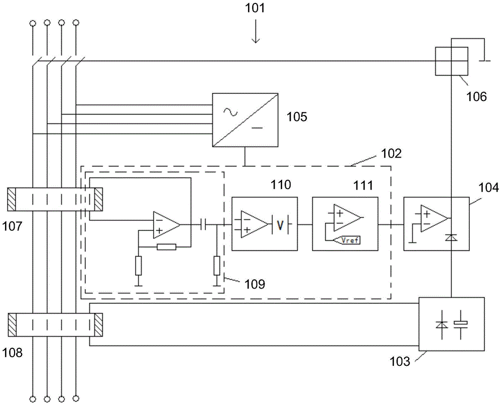
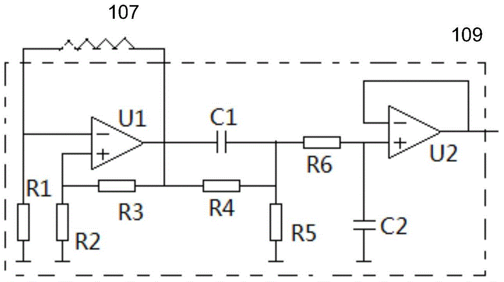
[0025] refer to figure 1 As shown, the present invention proposes a residual current protection device, figure 1 A schematic diagram of the electrical structure of the residual current protection device is disclosed. The residual current protection device includes a first detection core 107 , a second detection core 108 , a first fault current detection circuit 102 , a second fault current detection circuit 103 , a drive circuit 104 and a bipolar power supply module 105 .

[0026] The first detection magnetic core 107 is carried around the main loop wire. The first fault current detection circuit 102 is coupled to the first detection magnetic core 107. The first fault current detection circuit 102 relies on the grid voltage to sample the full current of the main circuit to detect high-frequency AC fault residual current, pulsating DC residual current and smooth DC residual current.

[0027] The second detection core 108 is also carried around the main loop wire. The second...


PUM


Abstract

A residual current protection device, comprising: a first detection magnetic core (107) and a second detection magnetic core (108) which are borne around a conducting wire of a main loop; a first fault current detection circuit (102) coupled with the first detection magnetic core (107), wherein the first fault current detection circuit (102) is dependent on a grid voltage and conducts full current sampling on the main loop, so as to detect a high-frequency alternating current fault residual current, a pulse direct current residual current and a smooth direct current residual current; a second fault current detection circuit (103) coupled with the second detection magnetic core (108), wherein the second fault current detection circuit (103) conducts electromagnetic current sampling on the main loop independent of the grid voltage, so as to detect a power-frequency alternating current residual current and a pulse direct current residual current; a drive circuit (104), wherein the input thereof is connected to the first fault current detection circuit (102) and the second fault current detection circuit (103), and the output thereof is connected to an executing mechanism (106) to trigger the executing mechanism (106) to act; and a bipolar power source module (105) connected to the main loop and the first fault current detection circuit (102).

Description

technical field [0001] The present invention relates to a current protection device, more specifically, to a residual current protection device sensitive to full current. Background technique [0002] Realizing current protection by monitoring the residual current is an important protection measure in electrical circuits. The existing technology mainly uses the excitation circuit to generate high-frequency current in the magnetic core, thereby generating a high-frequency magnetic field. When the primary coil has low-frequency or DC current When, it can cause the change of the saturation degree of the magnetic circuit and the deviation of the high-frequency magnetic field to measure the DC current. [0003] For example, the Chinese patent application with publication number CN1387213A titled "Detection Transformer for Earth Leakage Protection Device and Earth Leakage Protection Device" discloses an earth leakage fault current detection transformer in the form of an annular ir...

Claims


Application Information

Patent Timeline
Patent Type & Authority Applications(China)
IPC IPC(8): H02H3/32G01R19/00
CPCH02H1/003H02H3/332H02H3/347
Inventor 陈永亮徐磊陈黎俊杨世江
Owner SEARI ELECTRIC TECH
Why Eureka
Try Eureka