
An ultrasonic phased array automatic flaw detection machine for railway vehicle axles

A technology for railway vehicles and phased array probes, which is applied in the direction of using sonic/ultrasonic/infrasonic waves to analyze solids, can solve the problems of low detection efficiency and accuracy, labor-intensive operators, and inability to adapt to railway vehicles, etc., to achieve detection efficiency and high accuracy, improve maintenance quality, and reduce the effect of wheel and axle maintenance process time

Active Publication Date: 2017-12-19
SHEYANG SAIFU NDT EQUIP MFG
View PDF8 Cites 0 Cited by
  • Summary
  • Abstract
  • Description
  • Claims
  • Application Information

AI Technical Summary

Problems solved by technology

[0003] At present, most of the ultrasonic flaw detection for passenger wheel axle maintenance in my country has imported phased array ultrasonic flaw detection equipment from abroad, while the ultrasonic flaw detection technology for truck axles is still stagnant, and only ordinary ultrasonic flaw detection technology can be used, which requires manual operation, and the detection efficiency and accuracy are high. Low, the labor intensity of operators is high, and there are many unstable factors, which cannot meet the needs of the high-speed operation and development of China's railway vehicles, and have played a certain role in hindering the development of my country's railway vehicles

Method used


Image

  • An ultrasonic phased array automatic flaw detection machine for railway vehicle axles
  • An ultrasonic phased array automatic flaw detection machine for railway vehicle axles
  • An ultrasonic phased array automatic flaw detection machine for railway vehicle axles

Examples


Embodiment Construction

[0027] The present invention will be further described in detail below in conjunction with the accompanying drawings and specific embodiments.

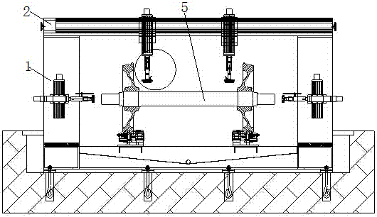
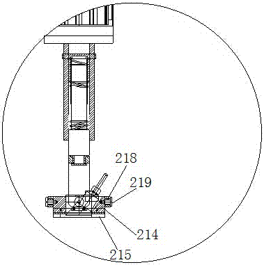
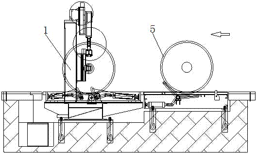
[0028] as attached Figure 1-10An ultrasonic phased array automatic flaw detection machine for a railway vehicle wheel axle shown in the present invention includes a bed body 1, a module beam 2, a follower device, a centering device, an A-type probe 3, and a phased array probe 4 , a wheel shaft rotation mechanism, a loading and unloading mechanism, and a phased array ultrasonic flaw detector located on the bed body 1; a module beam 2 is provided above the bed body 1; Two relative follow-up devices; the follow-up devices are located at the two ends of the inner side of the wheel shaft to be measured; the phased array probe 4 is arranged below the follow-up device, and can move circumferentially through the follow-up device; the There are centering devices on both sides of the bed body 1 that can move up and down; the A-type probe 3 is...


PUM


Abstract

The invention relates to an ultrasonic phased array automatic flaw detector for railway vehicle axles. A die set cross beam is arranged above a lathe bed main body; the die set cross beam is provided with two follow-up devices which can transversely move and are oppositely arranged; the follow-up devices are respectively located at two ends of the inner side of a to-be-detected axle; a phased array is arranged below each follow-up device; two sides of the lathe bed main body are respectively provided with an alignment device capable of vertically moving; an A-type probe is arranged at one end of each alignment device, and can transversely move through the corresponding alignment device; the middle part of the lathe bed main body is provided with an axle rotating mechanism; the lathe bed main body is also provided with a feeding and blanking mechanism, and the feeding and blanking mechanism is used for axle feeding and blanking; the A-type probes and the phased array probes are connected with the phased array ultrasonic flaw detector. According to the ultrasonic phased array automatic flaw detector for the railway vehicle axles, disclosed by the invention, three-dimensional display can be performed on flaws; meanwhile, by adopting cross scanning of the phased array flaw detection and A-type probe flaw detection, the detection efficiency and the detection accuracy are high, the production cost is low, and the application prospect is wide.

Description

technical field [0001] The invention relates to the technical field of metal flaw detection, in particular to an ultrasonic phased array automatic flaw detection machine for railway vehicle axles. Background technique [0002] With the rapid development of high-speed railways in the world, in order to adapt to the development of the national economy and meet the needs of the people, my country's railway industry is developing vigorously. In railway transportation, safety is the top priority. The operation of railway vehicles is directly related to the safety of people's lives and property. Therefore, after a certain period of operation, the running part and braking part of the vehicle must be disassembled, inspected and repaired. Eliminate some parts that no longer meet the standards. The quality of the vehicle axle is particularly important. If there is a crack in the vehicle axle, it may break during the operation of the vehicle and cause serious losses. Only after passing...

Claims


Application Information

Patent Timeline
Patent Type & Authority Patents(China)
IPC IPC(8): G01N29/06
Inventor 杨建
Owner SHEYANG SAIFU NDT EQUIP MFG
Learn More