
A device for testing the outlet flow rate of the main oil passage of a planetary transmission mechanism

A technology of planetary speed change and outlet flow, applied in the direction of machine gear/transmission mechanism testing, etc., can solve the problems of inability to observe the flow state of lubricating oil flow field, not considering the influence of the main oil passage, etc., to achieve simple and easy installation and maintenance, and improve the reliability. Reliability, promising effect

Active Publication Date: 2017-11-07
BEIJING INSTITUTE OF TECHNOLOGYGY
View PDF11 Cites 0 Cited by
  • Summary
  • Abstract
  • Description
  • Claims
  • Application Information

AI Technical Summary

Problems solved by technology

For example, there are certain limitations in the patent’s use of plastic hoses to replace the lubricating oil passage of the transmission. The patent does not consider the impact of the high-speed rotation of the main oil passage on the lubrication flow, and the device cannot observe the flow field of the lubricating oil in the main oil passage under high-speed rotation. flow state

Method used


Image

  • A device for testing the outlet flow rate of the main oil passage of a planetary transmission mechanism
  • A device for testing the outlet flow rate of the main oil passage of a planetary transmission mechanism
  • A device for testing the outlet flow rate of the main oil passage of a planetary transmission mechanism

Examples


Embodiment 1

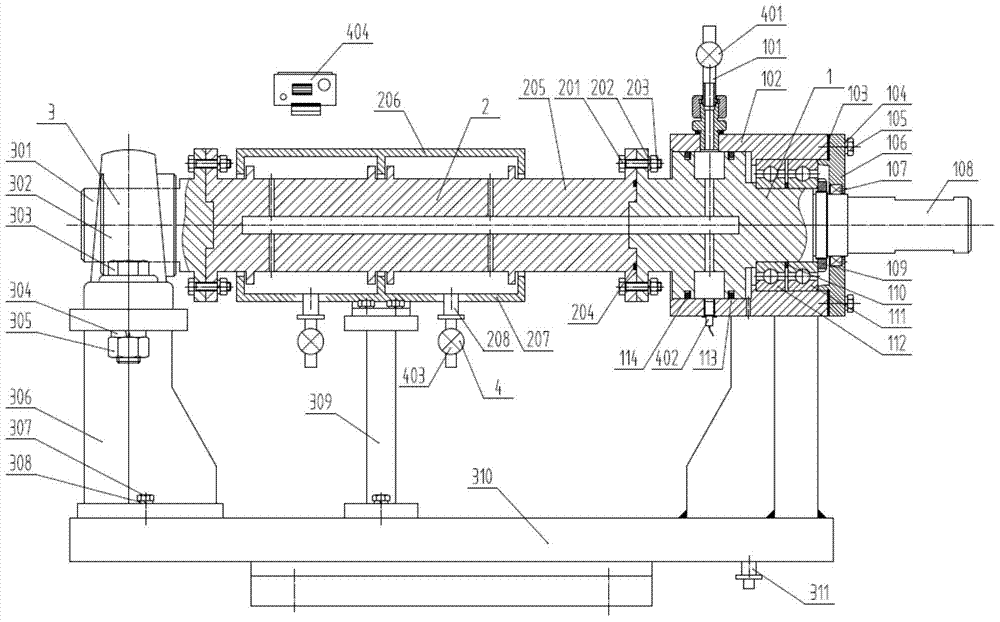
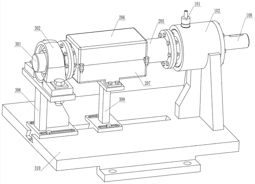
[0052] The drive assembly 1 includes an oil inlet pipe assembly 101, a bearing seat 102, a gasket 103, a spring washer I104, a screw I105, a bearing end cover 106, a lip seal 107, an input shaft 108, a pressure plate 109, a shaft sleeve 110, a bearing A111, bearing B112, sealing ring A113 and sealing ring B114;

[0053] The bearing seat 102 is a cylinder with a stepped hole, and two radial through holes are opened on the outer peripheral surface of the cylinder along its circumference;

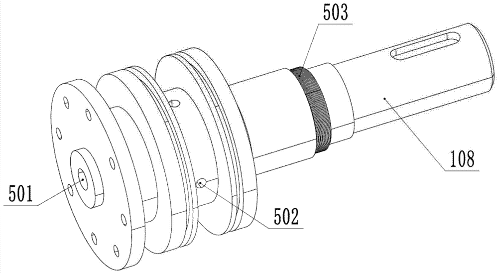
[0054] See attached image 3 , the input shaft 108 is a stepped shaft with a blind hole along its axial direction, an annular groove along the circumference of the large diameter section of the stepped shaft, and an annular groove along the bottom surface of the annular groove. The radial through holes distributed in the circumferential direction, the radial through holes and the blind holes are connected to form the oil inlet hole 502; the middle part of the input shaft 108 is processed with...

Embodiment 2

[0074] Drive assembly 1, support assembly 3 and measuring instrument assembly 4 in the present example are all identical with the structure in embodiment 1; See attached Figure 5 , the length of the test shaft 205 in the present embodiment increases, the number of oil outlet holes 504 increases, and the length of the corresponding test case loam cake 206 and the test case base 207 also increases, and the test case base 207 is installed The number of the oil outlet pipe assembly 208 increases, and the number changes from 2 to 5.


PUM


Abstract

The invention discloses a flow test device for the outlet flow of a main oil channel of a planetary transmission mechanism, which belongs to the technical field of lubrication systems of a planetary transmission mechanism, and comprises: a drive assembly, a test assembly, a support assembly and a measuring instrument assembly; the drive assembly realizes the test assembly The power transmission is provided, and an oil inlet hole is provided to supply oil to the test assembly; the test assembly is used to simulate the flow state of lubricating oil in the main oil passage of the planetary transmission mechanism. There is a main oil passage inside the test assembly, and the main oil passage is connected to the The oil inlet hole of the drive assembly is connected, and the oil outlet hole is provided on the main oil passage; the support assembly realizes the support of the drive assembly and the test assembly; the measuring instrument assembly realizes the measurement of the flow rate and pressure of each inlet and outlet of the main oil passage ; The device table has a simple structure, low cost, good versatility, simple and easy installation and maintenance.

Description

technical field [0001] The invention belongs to the technical field of lubrication systems of planetary transmission mechanisms, and in particular relates to a flow testing device for the outlet flow of a main oil channel of a planetary transmission mechanism. Background technique [0002] The planetary transmission mechanism has many advantages such as high transmission efficiency, small size, large transmission ratio, stable movement, strong impact resistance, and strong anti-vibration ability. It is widely used in many industrial production fields such as petroleum, mining, construction machinery, and automobiles. An important component in the powertrain. [0003] The lubrication system is an important component of the planetary transmission mechanism, and its main function is to supply lubricating oil with suitable pressure and flow rate for each moving friction pair in the transmission mechanism. The performance of the lubrication system is the main factor affecting th...

Claims


Application Information

Patent Timeline
Patent Type & Authority Patents(China)
IPC IPC(8): G01M13/02
Inventor 吴维熊钊苑士华胡纪滨
Owner BEIJING INSTITUTE OF TECHNOLOGYGY
Learn More