
Iron driller automatic centering method

An iron driller and automatic technology, which is applied in the field of automatic centering of iron drillers, can solve the problems of complex structure and inability to find left and right, and achieve the effects of wide application range, improved centering accuracy and automation, and less damage

Inactive Publication Date: 2017-08-04
SANY GRP
View PDF6 Cites 0 Cited by
  • Summary
  • Abstract
  • Description
  • Claims
  • Application Information

AI Technical Summary

Problems solved by technology

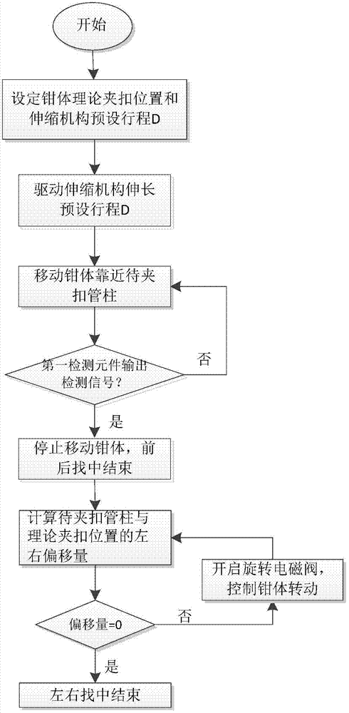
When the roller touches the drill pipe, the spring is compressed to make the telescopic shaft retreat until its retreat displacement is equal to the initial set displacement, which is regarded as centering; the technical scheme has a complex structure, and can only achieve front and rear centering, and cannot perform left and right centering

Method used


Image

  • Iron driller automatic centering method
  • Iron driller automatic centering method
  • Iron driller automatic centering method

Examples


Embodiment Construction

[0045] It should be noted that, in the case of no conflict, the embodiments of the present invention and the features in the embodiments can be combined with each other. The present invention will be described in detail below with reference to the accompanying drawings and examples.

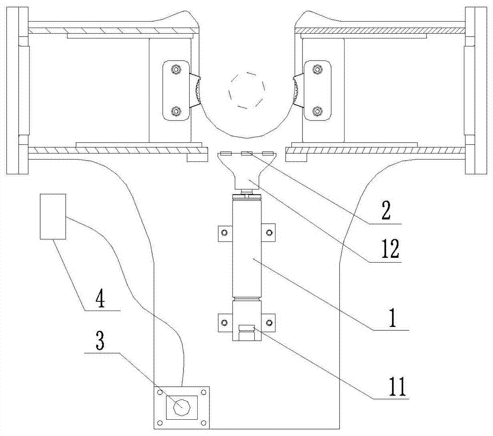
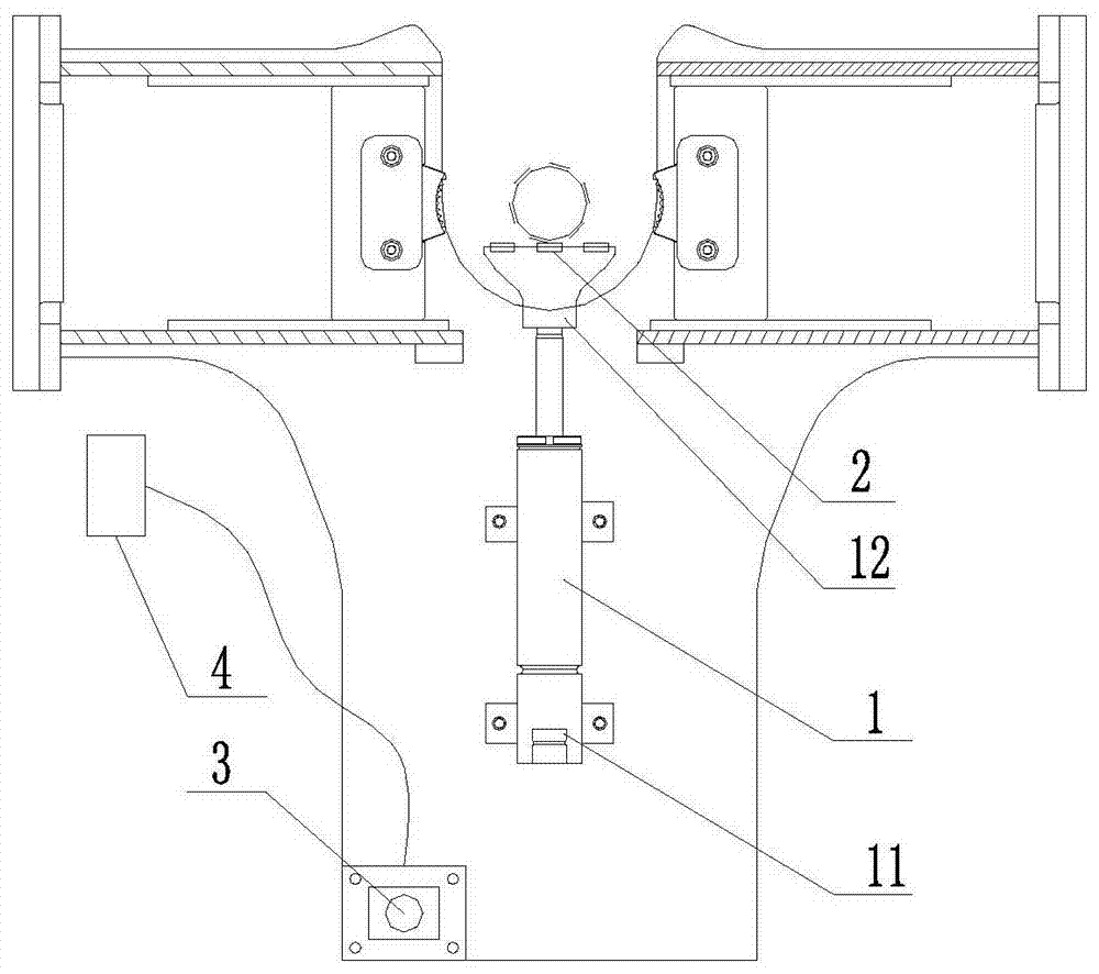
[0046] In the present invention, the orientations used such as "front", "rear", "left", and "right" all use figure 1 The views shown are for reference, specifically, towards figure 1 , figure 1 Above is front, below is back, left is left, and right is right. The terms "first" and "second" are mainly used to distinguish different components, but do not specifically limit the components.

[0047] figure 1 , figure 2 Shown is the structural representation of the iron driller's centering device of the present invention, wherein figure 1 Shown is the structural schematic diagram of the iron driller's centering device in the initial state, figure 2 Shown is a schematic structural view of the i...


PUM


Abstract

The invention discloses an automatic centering device for a steel drilling tool. The device comprises a telescoping mechanism, a first detecting element and a control device, wherein the first end of the telescoping mechanism is fixedly arranged on a steel drilling tool clamp body, and while the second end is provided with at least one first detecting element; the telescoping mechanism is used for changing the position of the first detecting element on the steel drilling tool clamp body; the first detecting element is used for detecting a pipe column to be clamped as the steel drilling tool clamp body moves and outputting a detecting signal while detecting the pipe column to be clamped; the control device is connected with the first detecting element and used for controlling the movement state of the steel drilling tool while receiving the detecting signal outputted by the first detecting element, so that the pipe column to be clamped can be kept in the theoretic clamping position of the steel drilling tool clamp body. The invention further provides an automatic centering method for the steel drilling tool. With the adoption of the device and the method, the steel drilling tool clamp body can be automatically centered according to the position of the pipe column to be clamped; the automation degree is high; the applicable scope is wide.

Description

technical field [0001] The invention relates to the field of petroleum equipment, in particular to an automatic centering method for iron drillers. Background technique [0002] Iron Driller is a safe and efficient drilling tool hook-up and breakout equipment. It mainly includes a boom device and a tong body. Through the multi-degree-of-freedom movement of the boom device, the tong body is driven to move to the target drill pipe, and then the The pliers hold the drill pipe tightly and complete the make-up or breakout between two drill pipes. [0003] Iron drillers need to center the target drill pipe when making up and breaking out. At present, it is generally completed by manual assistance, which not only increases the work intensity of the operator, affects the centering accuracy of the iron driller, but also limits the accuracy of the iron driller. Improvement in the degree of automation. With the continuous improvement of the intelligent and unmanned requirements of ir...

Claims


Application Information

Patent Timeline
Patent Type & Authority Patents(China)
IPC IPC(8): E21B19/16
Inventor 范吉祥赵勇刘强程建民
Owner SANY GRP
Learn More