
Ultra-stabilization treatment method of high-rare-earth-content in-situ crystallization catalyst

A technology with high rare earth content and in-situ crystallization, applied in physical/chemical process catalysts, molecular sieve catalysts, chemical instruments and methods, etc.

Active Publication Date: 2015-09-23
湖北赛因斯科技开发有限公司
View PDF11 Cites 5 Cited by
  • Summary
  • Abstract
  • Description
  • Claims
  • Application Information

AI Technical Summary

Problems solved by technology

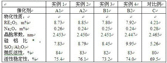
CN1913965A reported that the rare earth content of the in-situ catalyst can reach 12%, but the rare earth content is less than 3% when preparing ultra-stable catalyst products with low unit cell constant, and the unit cell constant is around 2.450nm
For high rare earth content, such as rare earth is higher than 7m%, the ultra-stabilization treatment process of the catalyst has not been seen in the literature and related patent reports

Method used


Image

  • Ultra-stabilization treatment method of high-rare-earth-content in-situ crystallization catalyst
  • Ultra-stabilization treatment method of high-rare-earth-content in-situ crystallization catalyst
  • Ultra-stabilization treatment method of high-rare-earth-content in-situ crystallization catalyst

Examples


example 1

[0034] (1) Ammonium exchange

[0035]Add 1200g of deionized water to the stainless steel kettle, add 300g of in-situ crystallization NaY catalyst and 90g of ammonium chloride under stirring conditions, adjust the pH value to 3.0-4.0 with 4% dilute hydrochloric acid solution, and exchange at 80°C for 40 minutes , filtered, and the filter cake was rinsed with deionized water, and exchanged again in the same way to obtain Na 2 NH with O content below 4.0m% 4 Y-type catalyst.

[0036] (2) Rare earth exchange

[0037] Add 1200g of deionized water to the above product, add RECl 3 Rare earth (RE 2 o 3 8% of the weight of the catalyst) solution, at a pH of 3.0-4.0, exchanged for 40 minutes at 80°C to obtain REY and NH 4 Type Y catalyst mixture.

[0038] (3) Once roasted

[0039] The above mixture was hydrothermally calcined at 550° C. for 4 hours.

[0040] (4) Rare earth supplementation for materials after first roasting

[0041] Add 1200g of deionized water and 60g of ammon...

example 2

[0047] According to the method of Example 1, the in-situ crystallized NaY type product is subjected to ultra-stabilization modification treatment: wherein the step (5) roasting temperature gradient is: the filter cake is roasted at 550°C for 2 hours, and then heated to 850°C and then roasted for 2 hours. Other conditions are the same as example 1 to obtain catalyst A2.

example 3

[0049] (1) Ammonium exchange

[0050] Add 1200g of deionized water to the stainless steel kettle, add 300g of in-situ crystallization NaY catalyst and 90g of ammonium chloride under stirring conditions, adjust the pH value to 3.0-4.0 with 4% dilute hydrochloric acid solution, and exchange at 80°C for 40 minutes , filtered, and the filter cake was rinsed with deionized water, and exchanged again in the same way to obtain Na 2 NH with O content below 4.0m% 4 Y-type catalyst.

[0051] (2) Rare earth exchange

[0052] Add 1200g of deionized water to the above product, add RECl 3 Rare earth (RE 2 o 3 6% by weight of the catalyst) solution, exchanged for 40 minutes at pH 3.0-4.0, 80°C, to obtain REY type and NH 4 Type Y catalyst mixture.

[0053] (3) Once roasted

[0054] The above mixture was fired at 550°C for 4 hours.

[0055] (4) Rare earth supplementation for materials after first roasting

[0056] Add 1200g of deionized water and 60g of ammonium chloride to the above...


PUM

PropertyMeasurementUnit
Cell constantaaaaaaaaaa

Abstract

The invention discloses an ultra-stabilization treatment method of a high-rare-earth-content in-situ crystallization catalyst. The ultra-stabilization treatment method includes that the ultra-stabilization catalyst high in rare earth content and lower than 2.455nm in lattice constant is prepared by high-temperature hydrothermal calcining of NaY-type catalyst for in-situ crystallization under different temperature gradient conditions after multiple times of exchange of ammonium ions and rare earth ions. The high-rare-earth-content in-situ crystallization catalyst has the advantages of high rare earth content, high silicon-aluminum ratio, high activity, high stability and excellent coke selectivity.

Description

technical field [0001] The invention relates to an ultra-stabilization treatment method of an in-situ crystallization catalyst, more specifically, an ultra-stabilization treatment method of an in-situ crystallization catalyst with high rare earth content. Background technique [0002] From the emergence of molecular sieve catalytic cracking (FCC) catalysts in 1960 to the present, the preparation process of Y-type molecular sieve FCC catalysts can be roughly classified into two types: (a) molecular sieves are prepared separately and then compounded with carriers; (b) molecular sieves are made of natural kaolin Bit crystallization, part of the kaolin is transformed into Y zeolite, and part of the kaolin is used as a carrier. [0003] The former method, the preparation of the catalyst, is to beat the active component and the carrier (filler and binder) together, and spray dry it to form a microsphere catalyst with a particle size of 0-150 microns and an average particle size of...

Claims


Application Information

Patent Timeline
IPC IPC(8): B01J29/08
Inventor 潘红霞
Owner 湖北赛因斯科技开发有限公司
Learn More