
Cylindrical roller bearing with integrated speed change function for small load

A cylindrical roller bearing, small load technology, applied in the direction of roller bearings, rotating bearings, bearings, etc., can solve the problems of complex internal structure of the machine, and achieve fast response, high shear yield stress and low energy consumption. Effect

Inactive Publication Date: 2015-09-16
孙美娜
View PDF6 Cites 2 Cited by
  • Summary
  • Abstract
  • Description
  • Claims
  • Application Information

AI Technical Summary

Problems solved by technology

[0002] With the continuous advancement of science and technology, the efficiency of mechanical equipment has become a hot topic in the industry. Especially in many small and medium-sized enterprises that focus on production, the concept of quantity is very important. In this case, they have invested a certain amount of time. The cost is used to improve the operating efficiency of the machine. However, some improved machines have more complicated internal structures, or various external hydraulic and pneumatic systems for speed regulation.

Method used


Image

  • Cylindrical roller bearing with integrated speed change function for small load
  • Cylindrical roller bearing with integrated speed change function for small load

Examples


Embodiment Construction

[0009] The present invention will be described in further detail below in conjunction with the accompanying drawings and embodiments.

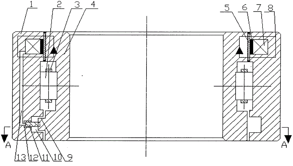
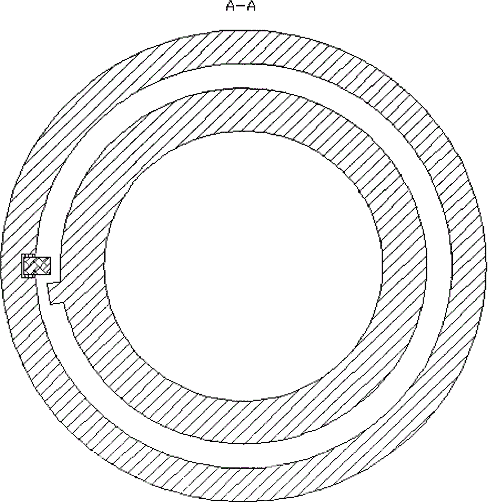
[0010] combine figure 1 and figure 2 , the present invention is used for a small load cylindrical roller bearing with integrated speed change function, the device is mainly composed of outer ring 1, rolling element 2, cage 3, inner ring 4, magnetorheological fluid 5, spacer ring 6, The coil 7, the piezoelectric ceramic 11 and the insulator 12 are composed. There are two annular grooves on the inner wall of the outer ring 1, one of which is wound with the electromagnetic coil 7, and the other annular groove 10 is installed with a piezoelectric ceramic 11, and the outer ring 1 is isolated from the piezoelectric ceramic 11 by an insulator 12; The inner ring 1, the outer ring 4 and the isolation ring 6 form a sealed cavity in which the magneto-rheological fluid 5 is sealed, and the magneto-rheological fluid 5 is isolated from the electromagneti...


PUM


Abstract

The invention relates to a cylindrical roller bearing with an integrated speed change function for a small load. The cylindrical roller bearing is mainly used for adjusting the speed distribution condition of a mechanism during operation in a cycle under the condition of the small load. The cylindrical roller bearing comprises an outer ring, a rolling body, a retaining rack, an inner ring, magnetorheological fluid, an isolating ring, an electromagnetic coil, piezoelectric ceramics and an insulator. Two annular grooves are formed in the internal wall of the outer ring, one annular groove is wound with the electromagnetic coil, the piezoelectric ceramics are mounted in the other annular groove, and the outer ring and the piezoelectric ceramics are isolated by the insulator; a sealed chamber is formed by the inner ring, the outer ring and the isolating ring, and the magnetorheological fluid is sealed in the sealed chamber and is isolated from the electromagnetic coil by the isolating ring; the external wall of the inner ring is provided with a non-annular small boss which is mounted in a manner that the small boss does periodic motion in the annular groove with the piezoelectric ceramics; a passage is formed between the electromagnetic coil and the piezoelectric ceramics and is used for enabling the positive and negative poles of the piezoelectric ceramics to be in conduction with the two ends of the electromagnetic coil.

Description

technical field [0001] The present invention relates to cylindrical roller bearings, and more particularly to cylindrical roller bearings for small loads with an integrated speed change function. Background technique [0002] With the continuous advancement of science and technology, the efficiency of mechanical equipment has become a hot topic in the industry. Especially in many small and medium-sized enterprises that focus on production, the concept of quantity is very important. In this case, they have invested a certain amount of time. The cost is used to improve the operating efficiency of the machine. However, the internal structure of some improved machines is more complicated, or various hydraulic and pneumatic systems are added externally for speed regulation. If there is a set of devices, without changing the original mechanical structure of the machine or adding an external speed-adjusting hydraulic or pneumatic system, only one part inside the machine can be repl...

Claims


Application Information

Patent Timeline
IPC IPC(8): F16C19/22F16F9/53
CPCF16C19/26F16C27/045F16C41/001F16C2202/36F16C2300/02
Inventor 孙美娜
Owner 孙美娜
Learn More