Eureka AIR delivers breakthrough ideas for toughest innovation challenges, trusted by R&D personnel around the world.

Saw blade with feed limiter

A technology of limiter and saw blade, applied in the direction of manufacturing tools, metal sawing equipment, tools of sawing machines, etc.

Inactive Publication Date: 2015-09-16
IRWIN IND TOOL CO
View PDF0 Cites 2 Cited by
  • Summary
  • Abstract
  • Description
  • Claims
  • Application Information

AI Technical Summary

Problems solved by technology

However, none of these configurations prevent potential overfeeding problems

Method used


Image

  • Saw blade with feed limiter
  • Saw blade with feed limiter
  • Saw blade with feed limiter

Examples


Embodiment Construction

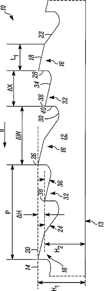
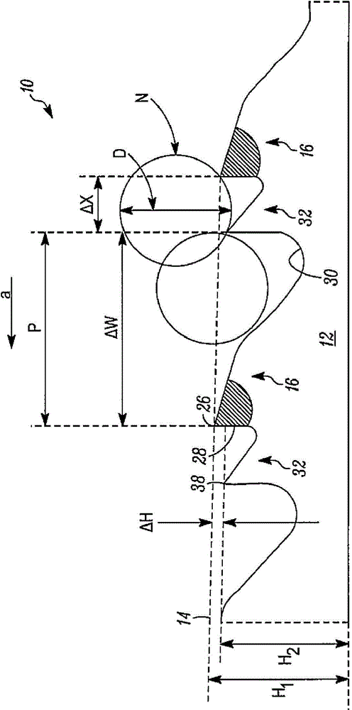
[0034] exist figure 1 , the first embodiment of the reciprocating saw blade is generally indicated by the reference numeral 10 . Saw blade 10 may be used in a reciprocating saw. The saw blade 10 includes a generally elongated blade body 12 having a back edge 13 and a cutting edge 14 extending along the cutting portion of the blade body 12 on the side of the blade body 12 opposite the back edge 13 and is bounded by a plurality of cutting teeth 16 (in this embodiment, a repeating pattern of teeth). Each tooth 16 includes a primary clearance surface 18 defining a primary clearance angle 20 between the primary clearance surface 18 and a plane parallel to the cutting edge 14, and a secondary clearance surface and a plane parallel to the cutting edge 14, a tip 26, at the tip 26 The secondary clearance surface 22 is the secondary clearance angle 24 between the rake face 28 on the side opposite the primary clearance surface 18 and the plane of the groove 30 . In other exemplary emb...


PUM


Abstract

A saw blade comprises cutting teeth, and the saw blade is further provided with at least one of cutting limiters which protrude from teeth or secondary teeth in grooves of the cutting teeth and are used for relieving too much feeding of a blade after configuration. It is required by the cutting limiters and / or the secondary teeth that in the cutting period, only a limited part of an object met by the saw blade falls under the cutting tip ends of the cutting teeth. The cutting limiters and / or the secondary teeth further assist the cutting teeth in cutting.

Description

technical field [0001] The present invention relates to saw blades, and more particularly to saw blades having chip restricting features to prevent overfeeding. Background technique [0002] A reciprocating saw is a hand-held power saw that includes a collet for releasably engaging a saw blade and driving the blade across a work piece in a reciprocating motion. The reciprocating motion can be an orbital cutting motion, a straight or linear cutting motion, or an angled cutting motion. The length or stroke of the reciprocating motion is typically about 1-1 / 2 inches or less. Reciprocating saws are sometimes referred to as "reciprocating" saws, jigsaws, and power hack saws, and the term reciprocating saw is used herein without limitation to refer to reciprocating saws, jigsaws and portable power bow saws. Reciprocating saws are typically powered by an electric motor (eg, corded or cordless) and pneumatically driven. Well known reciprocating saws are sold under the trade name...

Claims


Application Information

Patent Timeline
Patent Type & Authority Applications(China)
IPC IPC(8): B23D61/12
Inventor 阿西夫·埃利斯顿威廉·B·科布斯蒂芬·A·汉普顿道格拉斯·K·福斯伯格查尔斯·E·卡罗米尔斯
Owner IRWIN IND TOOL CO
Why Eureka
Eureka Blog
Learn More