Wire reeling device for electrocardiogram machine

A wire winding device, electrocardiogram machine technology, applied in medical science, sensors, diagnostic recording/measurement, etc., can solve the problems of shortened wire life, looseness, inconvenient use, etc., and achieve long wire life, convenient operation, and coil line order effect

Inactive Publication Date: 2015-09-16
潘庆玲
View PDF1 Cites 2 Cited by
  • Summary
  • Abstract
  • Description
  • Claims
  • Application Information

AI Technical Summary

Problems solved by technology

Its disadvantages are: when in use, first, because the 10 strands of wires are all wound on a rotating shaft, when one of the wires is drawn out, all other wires will also turn out with the rotation of the shaft, and as the first strand of wires are all wound It is turned out, although it will not be entangled, but it is inconvenient to use. It is necessary for the doctor to straighten each wire from the shell, which is inconvenient to use. Second, because the wire is wound on the shaft from the middle, no matter where Which end of the wire is extracted, the number of revolutions of the wire on the rotating shaft is always fixed. Therefore, the wire reel is not practical and cannot realize the function of reeling the wire; The rotating shaft is wound into a mallet shape, which is easy to loosen on the rotating shaft, and at the same time, it also greatly shortens the service life of the wire

Method used


Image

  • Wire reeling device for electrocardiogram machine
  • Wire reeling device for electrocardiogram machine
  • Wire reeling device for electrocardiogram machine

Examples


Embodiment Construction

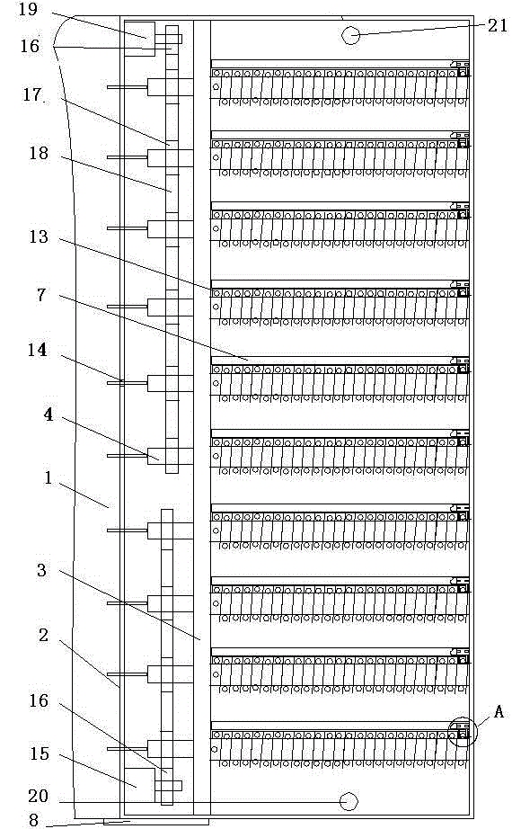
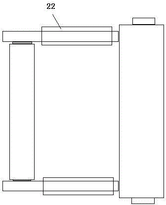
[0015] As shown in the accompanying drawings, a wire winding device for an electrocardiogram machine is provided with a casing 1, which is characterized in that a winding casing 2 is provided at the outlet end on the side of the casing 1, and a bracket 3 is arranged inside the winding casing 2. , rotating shaft 4, inner bearing seat, outer bearing seat, slideway 7, control device 8, thread guide 6 and transmission device, and described thread guide is made up of slide plate 9, roller shaft 10, strut 11 and pulley 12, The left and right ends of one side of the slide plate 9 are respectively provided with roller shafts 10, and the upper and lower ends are respectively provided with pulleys 12. The bottom surface is provided with ten parallel rectangular guide grooves 13, and the side is provided with ten threading holes 14. One side of the guide grooves 13 is provided with a rotating shaft 10, and the other side is provided with a slideway 7 along the line. The guide grooves 13 ...


PUM


Abstract

The invention discloses a wire reeling device for an electrocardiogram machine. The wire reeling device for the electrocardiogram machine is provided with a machine shell. The wire reeling device for the electrocardiogram machine is characterized in that the wire outlet end on the side face of the machine shell is provided with a wire reeling shell body, and a support, rotation shafts, inner bearing seats, outer bearing seats, sliding ways, wire smoothing devices and a transmission device are arranged in the wire reeling shell body; the two ends of roll shafts are connected with sliding plates, guide grooves are formed in the lower bottom face of the wire reeling shell body, wire penetrating holes are formed in the side face of the wire reeling shell body, one side of each guide groove is provided with one rotation shaft, the other side of each guide groove is provided with one wire smoothing slide way, one ends of the guide grooves are provided with the support, the inner end of each rotation shaft is connected with the support, and the outer end of each rotation shaft is connected with the wire reeling shell body; a wire board is spirally twisted on each rotation shaft, a wire inlet is axially formed in the center of the inner end of each rotation shaft, a wire outlet is radially formed in the end face of the inner end of each rotation shaft, and each wire inlet is communicated with the corresponding wire outlet; grooves between the wire boards are provided with the wire smoothing devices, one ends of the wire smoothing devices are connected with the sliding ways in a rolling mode, and the other ends of the wire smoothing devices abut against the rotation shafts between the wire boards through the roll shafts. The wire reeling device for the electrocardiogram machine has the advantages of being novel in structure, convenient to operate, orderly in wire reeling, long in wire service life and the like.

Description

technical field [0001] The invention relates to the technical field of electrocardiogram auxiliary equipment, in particular to a wire winding device for an electrocardiogram machine. Background technique [0002] The electrocardiogram examination is very frequent clinically in the hospital. There are 6 chest wires and 4 limb wires on the electrocardiogram machine. During frequent use, the wires are often entangled with each other, which brings a lot of inconvenience to the inspection. Kink, straighten the wires, and if you encounter a critical patient, it may be life-threatening due to delays in examination time and failure to diagnose the condition in time. [0003] CN202497148 discloses a wire winding device for an electrocardiogram machine. Its special feature is that the winding body is installed on the rotating shaft, the winding body and the rotating shaft are wrapped in the casing, one end of the rotating shaft protrudes from the casing, and the port is equipped with ...

Claims


Application Information

Patent Timeline
Patent Type & Authority Applications(China)
IPC IPC(8): A61B5/0402
Inventor 潘庆玲
Owner 潘庆玲
Why Eureka
Try Eureka