
Connection structure of tool bit and host of hair scissors

A connection structure and hair clipper technology, applied in metal processing and other directions, can solve the problems of poor safety, easily damaged parts of the cutter head, damaged components, etc., to avoid the loss of the cutter head, facilitate docking and fixation, and avoid being damaged.

Active Publication Date: 2015-09-09
NINGBO ZHENHE ELECTRICAL EQUIP
View PDF8 Cites 0 Cited by
  • Summary
  • Abstract
  • Description
  • Claims
  • Application Information

AI Technical Summary

Problems solved by technology

[0002] Currently on the market for the detachable head structure of hair scissors, the generally adopted scheme is that the head and the host are separated, that is, the head and the host are two independent individuals. This structure appears in the actual use process. Many shortcomings are mainly reflected in the fact that when cleaning the cutter head, the cutter head needs to be removed and rinsed with water, so that the cutter head and the host are separated. After cleaning the cutter head, the user sometimes reassembles the cutter head and the host when there is no rush. In this way, it is easy to lose the cutter head or the host, which will cause the product to be unusable and bring losses to the user;
[0003] Secondly, when disassembling the cutter head, relying on the hand to pull the cutter head off, not only is it easy to cause damage to the parts, but also the hand is easily cut by the cutter head, which is less safe;
[0004] Thirdly, the installation of the cutter head mainly depends on the experience of the user, it is easy to damage the cutter head or the parts on the host, and affect the service life of the hair clippers

Method used


Image

  • Connection structure of tool bit and host of hair scissors
  • Connection structure of tool bit and host of hair scissors
  • Connection structure of tool bit and host of hair scissors

Examples


Embodiment Construction

[0034] The present invention will be further described in detail below in conjunction with the accompanying drawings and specific embodiments.

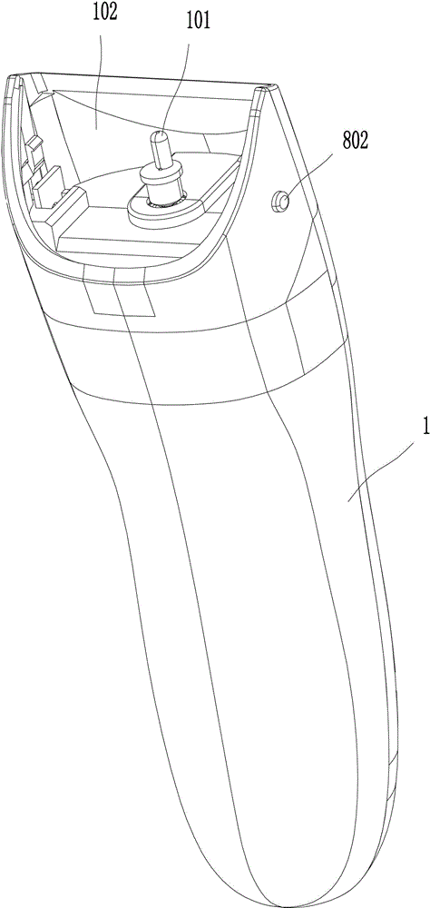
[0035] refer to Figure 1-15 Shown, the connecting structure of the cutter head of the barber scissors of the present invention and main frame, it comprises main frame 1 and cutter head 2, and main frame 1 comprises drive shaft 101, and drive shaft 101 is driven by motor, and cutter head 2 comprises movable blade 302, movable knife rest 3. The static blade 401 and the static blade holder 4, the static blade 401 is fixedly connected to the static blade holder 4, the moving blade 302 is fixedly connected to the moving blade holder 3, and the moving blade holder 3 and the moving blade 302 are installed on the static blade holder 4 , the movable blade 302 is stacked on the top of the static blade 401, and the movable blade 302 is provided with a knife pressing plate, and a torsion spring is installed on the static knife holder 4, and the ...


PUM


Abstract

The invention discloses a connection structure of a tool bit and a host of hair scissors. The connection structure comprises the host and the tool bit which is arranged at the front end of the host; the host comprises a driving shaft; the tool bit comprise a movable tool frame and a fixed tool frame; a sliding connection mechanism, a locking mechanism and a power mechanism are arranged between the fixed tool frame and the host; the sliding connection mechanism is used for enabling the tool bit to slide frontward and backward relative to the host so as to enable the tool bit to be in abutting joint with or separated from the host; the locking mechanism is used for locking the tool bit after the tool bit is in abutting joint with the host; the power mechanism is used for enabling the tool bit to automatically slide forward after the tool bit is unlocked so as to enable the tool bit to be separated from the host; the movable tool frame is provided with a shaft groove which is used for being inserted into the driving shaft. According to the connection structure of the tool bit and the host of the hair scissors, the tool bit is not separated from the host when the tool bit is cleaned and the tool bit detachment and installation is convenient and safe.

Description

technical field [0001] The invention relates to the technical field of hairdressing equipment, in particular to a connection structure between a cutter head and a host of haircutting scissors. Background technique [0002] Currently on the market for the detachable head structure of hair scissors, the generally adopted scheme is that the head and the host are separated, that is, the head and the host are two independent individuals. This structure appears in the actual use process. Many shortcomings are mainly reflected in the fact that when cleaning the cutter head, the cutter head needs to be removed and rinsed with water, so that the cutter head and the host are separated. After cleaning the cutter head, the user sometimes reassembles the cutter head and the host when there is no rush. In this way, it is easy to lose the cutter head or the host, which will cause the product to be unusable and bring losses to the user; [0003] Secondly, when disassembling the cutter head...

Claims


Application Information

Patent Timeline
IPC IPC(8): B26B19/38
Inventor 王保安戴沪杰
Owner NINGBO ZHENHE ELECTRICAL EQUIP
Learn More