Multiport terminal with current bars

A technology of connecting chambers and current bars, applied in the direction of conductive connections, connections, circuits, etc., to achieve the effect of eliminating the risk of heat generation

Inactive Publication Date: 2015-09-02
PHOENIX CONTACT GMBH & CO KG
View PDF6 Cites 0 Cited by
  • Summary
  • Abstract
  • Description
  • Claims
  • Application Information

AI Technical Summary

Problems solved by technology

[0002] A problem that often arises in electrical installation technology is the electrical connection of power units with individual connecting cables

Method used


Image

  • Multiport terminal with current bars
  • Multiport terminal with current bars

Examples


Embodiment Construction

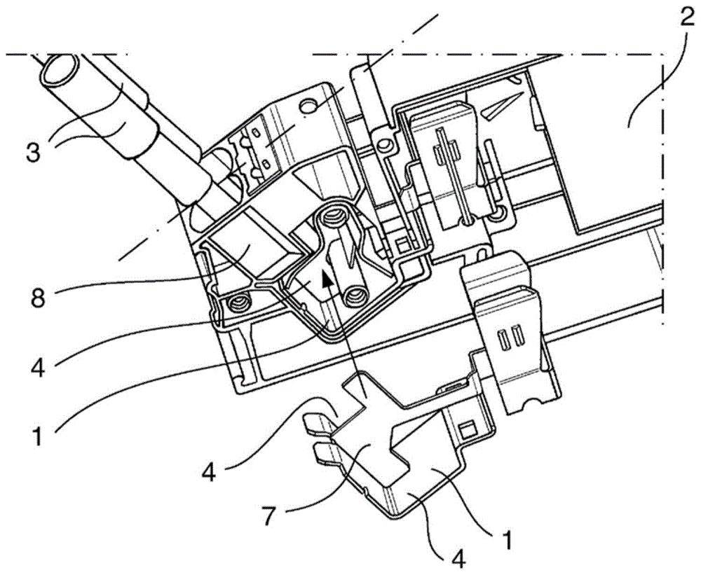
[0023] as attached figure 1 As can be seen in , the terminal housing 2 has a multiport connection chamber 1 into which the stripped ends of the cables 3 can be guided. The multiport connection chamber 1 has two connection chambers 4 separated from each other by a partition wall 7 .

[0024] The device formed as a stamped-bent-part combines the parts of the multiport connection chamber 1 with the partition wall 7, the parts of the contact terminal K for contacting the contact rail (not shown) in the terminal housing and Several components of the current bar 5 connected to the multiport connection chamber 1 and the contact terminals K.

[0025] attached figure 2 Shown is a multiport connection chamber 1 formed from a stamped and bent part with a partition wall 7 and a contact region K in which the tulip contact is formed by the two legs of the stamped and bent part. In the region between the multiport connection chamber 1 and the contact region K, punched-bent parts form the...


PUM


Abstract

The invention relates to a multiport terminal (1) with current bars (5) for receiving multiple cables to be connected to an electric unit. Multiple electrically conductive connection terminals (4) are provided for multiple cables, and the connection terminals (4) are connected to the current bars (5) in the electric unit in order to further establish an electric connection. According to the invention, the current bar (5) is designed so as to form multiple walls (6) of the connection terminals (4) and a separating wall (7) between the connection terminals (4). In this manner, an easily producible multiport terminal (1) is provided.

Description

technical field [0001] The invention relates to a device for receiving power cables, in particular as part of a connection device. Background technique [0002] A problem that often arises in electrical installation technology is the electrical connection of power units with individual connecting cables. [0003] For this purpose, various connection means are known in the prior art, such as screw terminals or insulation replaceable terminals. In this connection, the purpose of the connecting device is to securely contact the cable and to produce an electrical connection to the power unit. [0004] The connecting device usually has a connecting chamber, into which the cables are introduced for contacting. These connection chambers are usually designed to be electrically conductive, so that an electrically conductive connection between the cable and the power unit can be produced via the electrically conductive connection chambers and the conductors (so-called current bars) ...

Claims


Application Information

Patent Timeline
Patent Type & Authority Applications(China)
IPC IPC(8): H01R9/26
CPCH01R9/2608H01R4/4809H01R43/16H01R9/26H01R25/006
Inventor 福尔克尔·贾尔姆斯
Owner PHOENIX CONTACT GMBH & CO KG
Why Eureka
Try Eureka