An arc-extinguishing magnetic circuit with dislocation distribution of magnetic steel and its DC relay

A technology of dislocation distribution and magnetic steel, applied in electromagnetic relays, electromagnetic relay details, relays, etc., can solve the problems of small leakage flux, insufficient magnetic field strength, low magnetic utilization rate of magnetic steel, etc. Enhanced effect

Active Publication Date: 2017-07-28
XIAMEN HONGFA ELECTRIC POWER CONTROLS
View PDF6 Cites 0 Cited by
  • Summary
  • Abstract
  • Description
  • Claims
  • Application Information

AI Technical Summary

Problems solved by technology

In this four pieces of magnetic steel scheme, it is further proposed to increase the magnetic yoke 107 (as figure 2 shown), but the main magnetic flux 108 formed by the two magnetic steels 102 can only enhance the intensity of the arc-extinguishing magnetic field, and its leakage magnetic flux 109 also cancels each other in providing the ampere force to the moving spring. Therefore, the magnetic steel The magnetic utilization rate is relatively low
[0006] Additionally, if figure 1 As shown, the leakage magnetic flux 106 is generated between the adjacent magnetic steel 102 and the magnetic steel 103, because the magnetic steel 103 is in the middle of the length of the moving reed 101, and the distance between the magnetic steel 102 is relatively far, so Just make the leakage magnetic flux 106 relatively small, so that the magnetic field strength used to realize the arc extinguishing and the magnetic field strength used to provide the ampere force to the moving spring are not enough

Method used


Image

  • An arc-extinguishing magnetic circuit with dislocation distribution of magnetic steel and its DC relay
  • An arc-extinguishing magnetic circuit with dislocation distribution of magnetic steel and its DC relay
  • An arc-extinguishing magnetic circuit with dislocation distribution of magnetic steel and its DC relay

Examples


Embodiment 1

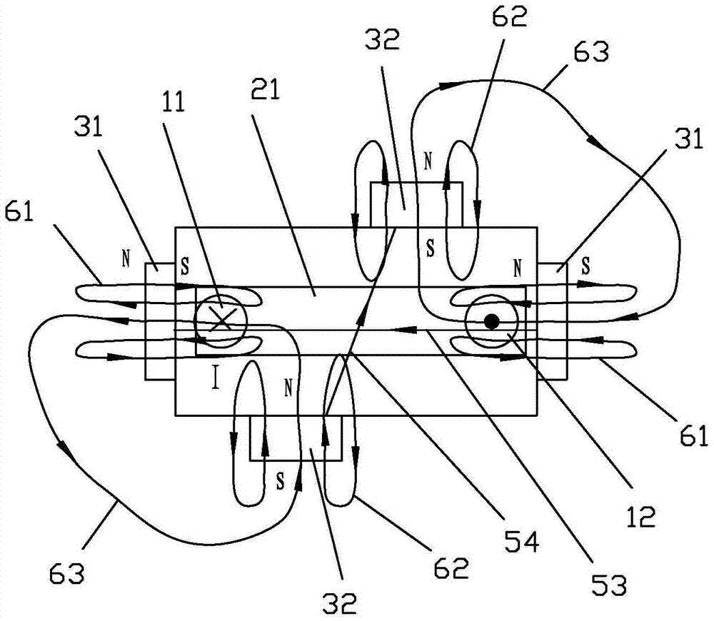
[0034] see image 3 As shown, the arc extinguishing magnetic circuit of a kind of magnetic steel dislocation distribution of the present invention includes a contact part, and the contact part includes two static contacts respectively used to provide current inflow and outflow, that is, the static contact 11 and the static contact 12 and a moving reed 21, the two ends of the moving reed 21 are respectively matched with two static contacts 11, 12, when the moving and static contacts are in contact together, the current I flows in from the static contact 11, After passing through the moving reed 21, it flows out from the static contact 12; a piece of first magnetic steel 31 is respectively provided on the outer sides of the two ends of the length of the moving reed 21; Two magnetic steels 32, wherein, the polarities of the two first magnetic steels 31 are opposite, and the polarities of the two second magnetic steels 32 are also opposite; the two second magnetic steels 32 are di...

Embodiment 2

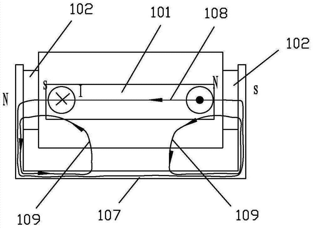
[0040] see Figure 4 to Figure 5 As shown, the arc extinguishing magnetic circuit with dislocation distribution of magnet steel in the present invention is different from the first embodiment in that the arc extinguishing magnetic circuit also includes two yoke clips 41 with magnetic conduction function, two The yoke clips 41 are respectively connected between the corresponding first magnetic steel 31 and the second magnetic steel 32; opposite sex. In this way, there are two groups of the first magnetic steel 31 and the second magnetic steel 32 connected with the yoke iron clip 41 around the mating periphery of the moving and static contacts.

[0041] Because of the yoke clip 41, the reluctance of the yoke clip is much smaller than the air reluctance. In this way, the magnetic flux of the magnet mainly goes to the yoke clip, so that the leakage flux between the two adjacent magnets becomes the main flux. In this way, the ampere force produced by the magnetic fields of the f...

Embodiment 3

[0048] see Figure 6 As shown, the arc-extinguishing magnetic circuit and the DC relay of a kind of magnetic steel misalignment distribution of the present invention are different from the first embodiment in that the two second magnetic steels 32 are respectively arranged on two static contacts The positions where the heads 11, 12 are in contact with the movable reed 21, that is to say, the two second magnets 32 are respectively distributed corresponding to the positions where the movable and static contacts are in contact. In this way, the second magnetic steel 32 is closer to the corresponding first magnetic steel 31, and the second magnetic steel 32 is facing the contacts, so that the intensity of the arc extinguishing magnetic field and the magnetic field providing the ampere force to the moving spring can be enhanced.


PUM


Abstract

Disclosed are an arc extinction magnetic circuit having misaligned magnetic steel and a direct-current relay thereof. The arc extinction magnetic circuit comprises a contact portion. The contact portion comprises two stationary contacts respectively for providing current inflow and outflow and a movable contact spring. Two ends of the movable contact spring respectively cooperate with the two stationary contacts. Each of the outer sides of the two ends in the length direction of the movable contact spring is respectively provided with a piece of first magnetic steel. Each of the outer sides of the two ends in the width direction of the movable contact spring is respectively provided with a piece of second magnetic steel, and the two pieces of second magnetic steel are misaligned. The two pieces of first magnetic steel face each other with opposite poles, and the two pieces of second magnetic steel also face each other with opposite poles. In the present invention, two pieces of magnetic steel in the middle in the length direction of the movable contact spring are misaligned, the distance between the two adjacent pieces of magnetic steel is reduced, the strength of a magnetic field between the two adjacent pieces of magnetic steel is then enhanced, thereby greatly enhancing the strength of an arc extinction magnetic field and the strength of the magnetic field which provides ampere force for the movable spring, and substantially increasing the magnetic utilization rate of the magnetic steel.

Description

technical field [0001] The invention relates to a DC relay, in particular to an arc-extinguishing magnetic circuit with dislocation distribution of magnetic steel and the DC relay, which are used for cutting off high-voltage and high-current DC loads. Background technique [0002] The relay is an electronic control device, which has a control system (also known as the input circuit) and a controlled system (also known as the output circuit), usually used in automatic control circuits, it actually uses a smaller current to control a larger An "automatic switch" of electric current. Therefore, it plays the role of automatic adjustment, safety protection, and conversion circuit in the circuit. DC relay is one of the relays. Most of the existing DC relays adopt the scheme of moving reed direct action (also known as solenoid direct action). For example, Hongfa, Tyco, Panasonic, LS and other manufacturers all use screw Straight line solution. [0003] The contact part of this k...

Claims


Application Information

Patent Timeline
Patent Type & Authority Patents(China)
IPC IPC(8): H01H50/38
CPCH01H50/38
Inventor 钟叔明施生圣
Owner XIAMEN HONGFA ELECTRIC POWER CONTROLS
Why Eureka
Try Eureka