On-site visitiation tooling

A tooling and on-site technology, which is applied in the field of measuring electric variable devices, can solve the problems that the sliding distance of the watch support cannot be accurately controlled and the connection structure is complicated.

Active Publication Date: 2015-09-02
浙江八达电子仪表有限公司 +2
View PDF8 Cites 0 Cited by
  • Summary
  • Abstract
  • Description
  • Claims
  • Application Information

AI Technical Summary

Problems solved by technology

However, the sliding distance of the existing watch support cannot be precisely controlled, and the connection structure with the tooling panel is complicated

Method used


Image

  • On-site visitiation tooling
  • On-site visitiation tooling
  • On-site visitiation tooling

Examples


Embodiment Construction

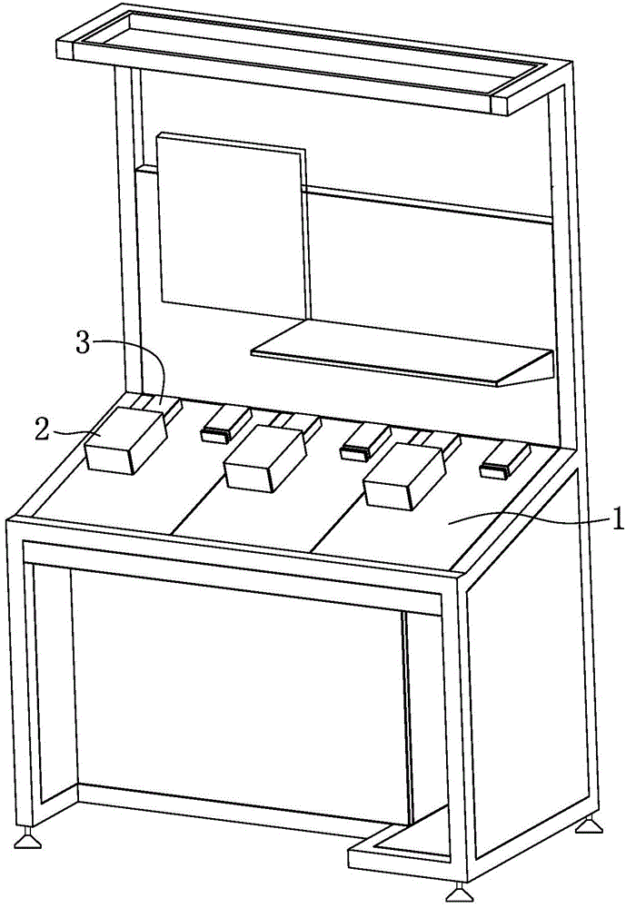
[0021] refer to figure 1 and figure 2 , tooling for on-site inspection, including a tooling panel 1 set at an inclination, a meter holder 5 is arranged on the tooling panel 1, and a pin 51 parallel to the tooling panel 1 is arranged on the upper end of the meter holder 5, and the meter holder 5 and the electric energy meter 2 conflict with each other , and, the pin 51 is inserted into the electric energy meter 2 to prevent the electric energy meter 2 from sliding along the tooling panel 1 .

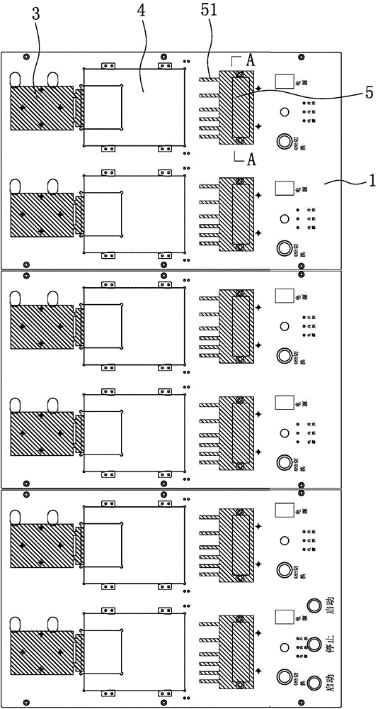
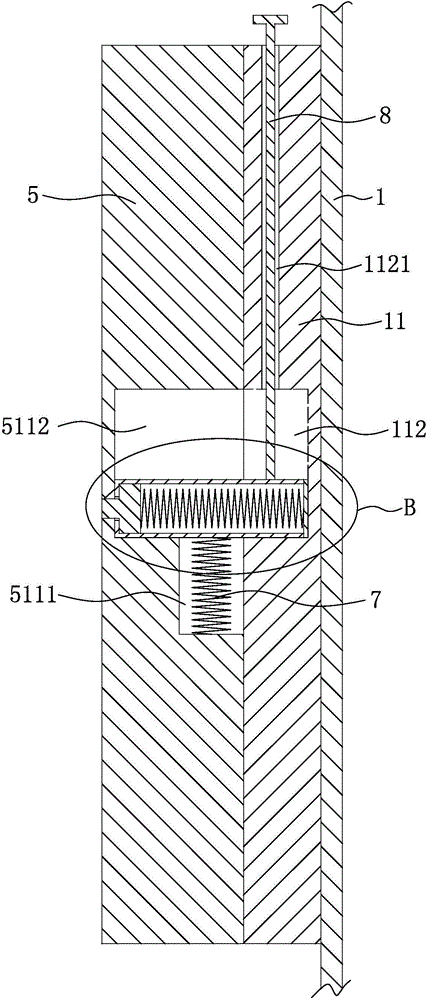
[0022] refer to image 3 , Figure 4 and Figure 5 The tooling panel 1 is provided with a guide groove 111 and a locking groove 112 communicating with the guide groove 111 on the end face of the tooling panel 1 facing the table holder 5. The guide groove 111 is vertically arranged to limit the sliding distance of the table holder 5 relative to the tooling panel 1, and the lock Tight grooves 112 are arranged laterally to prevent the watch holder 5 from sliding relative to the tooling ...


PUM


Abstract

The present invention relates to an on-site visitiation tooling which belongs to the measurement electrical variable device field, accurately limits the sliding distances of meter holders on a tooling panel, and simplifies a connection structure between the meter holders and the tooling panel. The on-site visitiation tooling comprises the inclined tooling panel, the tooling panel is equipped with the meter holders, and the upper ends of the meter holders are equipped with contact pins parallel with the tooling panel. The on-site visitiation tooling also comprises a limiting device, and the limiting device comprises a sleeve, a limiting rod and a first elastic element. The limiting rod and the first elastic element are located in the sleeve, and the first elastic element can push the limiting rod to move along the axial direction of the sleeve. The tooling panel is equipped with a guide grove and a locking groove communicated with the guide groove, the meter holders are equipped with the stepped holes, and each stepped hole comprises a first cavity matching the sleeve and a second cavity matching the limiting rod.

Description

technical field [0001] The invention relates to a tooling for on-site temporary inspection, which belongs to the field of electric variable measuring devices. Background technique [0002] Existing electric energy meters usually use on-site temporary inspection tooling to test their performance. The on-site temporary inspection tooling includes a tooling panel set at an angle. , in order to realize that the energy meter is fixed on the inclined tooling panel. However, the sliding distance of the existing table support cannot be precisely controlled, and the connection structure with the tooling panel is complicated. Contents of the invention [0003] The problem to be solved by the present invention is to provide a tool for on-site inspection, precisely limit the sliding distance of the watch holder on the tool panel, and simplify the connection structure between the watch holder and the tool panel. [0004] In order to solve the above problems, the utility model provide...

Claims


Application Information

Patent Timeline
Patent Type & Authority Applications(China)
IPC IPC(8): G01R35/04G01R1/04
Inventor 吴晓政张鹏飞庄方军杨江王礼飞孙雯姚诚金杰
Owner 浙江八达电子仪表有限公司
Why Eureka
Try Eureka