
Optical wavelength detector, optical wavelength detecting system and method

A detection system and optical wavelength technology, which is applied in the direction of transmitting sensing components with optical devices, can solve the problems of inability to realize multi-wavelength simultaneous detection output and inconvenience, and achieve the effects of convenient application, improved demodulation efficiency, and good synchronization effect

Active Publication Date: 2015-09-02
BEIJING UNIV OF POSTS & TELECOMM
View PDF3 Cites 4 Cited by
  • Summary
  • Abstract
  • Description
  • Claims
  • Application Information

AI Technical Summary

Problems solved by technology

In this technology, the optical wavelength detection (demodulation) of the measurement signal is the core of the optical sensing technology. The existing optical wavelength detection methods generally can only detect one specific wavelength information at a time, and cannot achieve multi-wavelength simultaneous detection output. Especially for broadband light sources, which contain many wavelengths, if using the existing wavelength detection technology, multiple detections are required to complete the demodulation of the wavelength, which brings inconvenience to practical applications

Method used


Image

  • Optical wavelength detector, optical wavelength detecting system and method
  • Optical wavelength detector, optical wavelength detecting system and method
  • Optical wavelength detector, optical wavelength detecting system and method

Examples


Embodiment Construction

[0040] In order to make the purpose, technical solutions and advantages of the embodiments of the present invention clearer, the technical solutions in the embodiments of the present invention will be clearly and completely described below in conjunction with the drawings in the embodiments of the present invention. Obviously, the described embodiments It is a part of embodiments of the present invention, but not all embodiments. Based on the embodiments of the present invention, all other embodiments obtained by persons of ordinary skill in the art without creative efforts fall within the protection scope of the present invention.

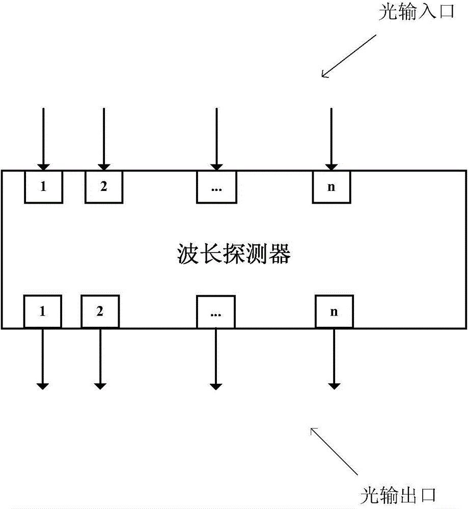
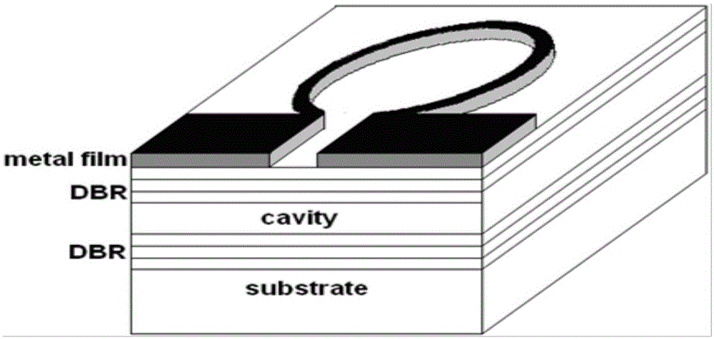
[0041] see figure 1 and figure 2 , the embodiment of the present invention proposes an optical wavelength detector, the optical wavelength detector is composed of n tunable F-P cavity filters arranged in parallel, and the thickness of the resonant cavity of the n tunable F-P cavity filters is distributed in steps;

[0042] One end of the optica...


PUM


Abstract

The invention provides an optical wavelength detector. The optical wavelength detector is formed by arranging n tunable F-P cavity filters in parallel. The resonant cavity thicknesses of the n tunable F-P cavity filters are characterized by step distribution. One end of the optical wavelength detector is provided with n optical input ports for receiving n paths of optical signals which serve as the inputs of the n tunable F-P cavity filters. The other end of the optical wavelength detector is provided with n optical output ports for outputting n paths of filtered transmitted optical signals. Under the control of an external tunable power supply, the n tunable F-P cavity filters make the F-P cavity filter passband wavelength periodically tuned. Simultaneous demodulation of multiple optical wavelengths can be achieved. Meanwhile, the optical wavelength detector has the characteristics of low cost, high integrated level, small volume and portability.

Description

technical field [0001] The invention relates to the technical field of optical fiber sensing, in particular to an optical wavelength detector, an optical wavelength detection system and a method. Background technique [0002] Optical fiber sensing technology was developed rapidly with the development of optical fiber communication technology in the 1970s. It uses light waves as the carrier and optical fiber as the medium to perceive and transmit external measured signals. As the signal carrier of the measured signal, the light wave is not afraid of electromagnetic interference, is easy to be received by various photodetection devices, can be easily converted into photoelectric or electro-optical, and is easy to match with highly developed modern electronic devices and computers. Optical fiber sensing technology, especially optical sensing technology based on fiber grating, has attracted more and more attention due to its superior performance. In this technology, the optical...

Claims


Application Information

Patent Timeline
Patent Type & Authority Applications(China)
IPC IPC(8): G01D5/353
Inventor 张治国孙艳飞李星谕陈雪王立芊张民
Owner BEIJING UNIV OF POSTS & TELECOMM
Learn More