
Engine lubrication system

A lubrication system and engine technology, applied in the direction of engine lubrication, engine components, machines/engines, etc., can solve the problems of high pressure, long oil passage, poor lubrication effect, etc., to ensure the lubrication effect, good lubrication effect, The result is a simple effect

Active Publication Date: 2015-09-02
重庆宗申航空发动机制造股份有限公司
View PDF6 Cites 7 Cited by
  • Summary
  • Abstract
  • Description
  • Claims
  • Application Information

AI Technical Summary

Problems solved by technology

The stroke of the oil channel in this lubricating structure is long, and the motion pair is lubricated by spraying, which requires a large pressure and the lubricating effect is not good

Method used


Image

  • Engine lubrication system
  • Engine lubrication system
  • Engine lubrication system

Examples


Embodiment 1

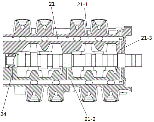
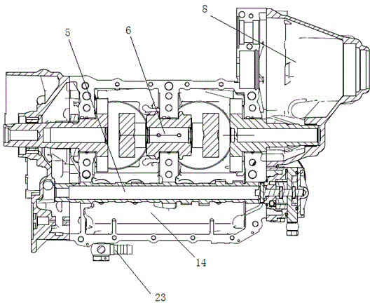
[0031] Embodiment 1, a kind of engine lubricating system, see figure 1 , figure 2 and Figure 4 , including a casing 20, the casing 20 is provided with a turbocharger 17, a lubricating oil tank 1, an oil cooler 2, an oil pump 3 and an oil filter 3-1 connected in sequence, and the oil filter 3-1 is connected with the casing The main oil passage 21 in 20 is connected; the box body 20 is provided with a crankshaft hole 6 and a camshaft hole 5, and the main oil passage 21 is connected with the crankshaft hole 6, the camshaft hole 5 and the two sides of the camshaft hole 5 for installing hydraulic jacks. The mounting hole 22 of the post communicates.

[0032] The crankshaft includes a front crankshaft, a middle crankshaft and a rear crankshaft, and the front crankshaft, the middle crankshaft and the rear crankshaft respectively include a main shaft 6-1 and a crank arm 6-6 and are connected as one by pressing the crank pin 6-2 on the main shaft 6-1. The crank pin 6-2 is rotation...

Embodiment 2

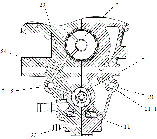
[0037] Embodiment 2, an engine lubrication system, on the basis of Embodiment 1, the main oil passage 21 includes an oil inlet section 21-1, an oil outlet section 21-2 and forms a U shape through a connecting section 21-3, the main oil passage 21 communicates with the crankshaft hole 6 and the camshaft hole 5 through the first oil hole 24; the two sides of the camshaft hole 5 are respectively provided with installation holes 22 for installing hydraulic tappets, and the installation holes 22 on one side are connected with the oil inlet section 21-1 communicated, and the mounting hole 22 on the other side communicates with the oil outlet section 21-2.

[0038] In order to achieve all-round lubrication, the oil inlet section 4-1 and the oil outlet section 4-2 are respectively provided with an oil hole 5 communicating with the crankshaft hole 2 and the camshaft hole 3 .

[0039] The hydraulic tappet 9 is connected to the rear end of the valve rocker arm 11 through a push rod 1...


PUM


Abstract

An engine lubrication system comprises a cabinet. A turbocharger, a lubricating oil tank, an oil cooler, an oil pump and an oil filter which are connected sequentially are arranged on the cabinet. The oil filter is connected with a main oil way in the cabinet. A bent axle hole and a camshaft hole are formed in the cabinet. The main oil way is communicated with the bent axle hole, the camshaft hole and mounting holes, used for mounting hydraulic tappets, on two sides of the camshaft hole. An oil storage tank communicated with the bent axle hole, the camshaft hole and the mounting holes is arranged at the bottom of the cabinet. An oil drainage hole is formed in the lower portion of the oil storage tank. The engine lubrication system is simple in structure, bent axle kinematic pairs, camshaft kinematic pairs and the like can be lubricated at different angles, and lubrication efficiency is improved.

Description

technical field [0001] The invention relates to an engine lubricating system, in particular to a multi-cylinder horizontally opposed engine lubricating system. Background technique [0002] The lubrication system is one of the important components of the engine. During the operation of the engine, the engine oil plays a very important role. It not only plays the role of lubrication, but also plays the role of sealing, cooling and buffering. The Chinese patent with application number 201220721229.0 discloses an engine lubricating structure, including an oil cylinder filter installed in the left box, an oil pump arranged on the right box, an oil filter arranged on the right box cover, and It is connected to the oil storage cavity at the oil cylinder filter, the oil pump, and the oil passage of the oil filter; the oil passage extends upwards from the oil filter, and extends above the crankshaft to the right box, Then extend upwards from the right case body to the cyl...

Claims


Application Information

Patent Timeline
IPC IPC(8): F01M1/06F01M9/10F01M1/04F01M1/02F01M1/10
Inventor 周丹刘政灿
Owner 重庆宗申航空发动机制造股份有限公司
Learn More