Mesh member, method of producing mesh member, and liquid discharging apparatus
A manufacturing method and net body technology, applied to the surface coating liquid device, spray device, printing device, etc., can solve problems such as damage, paper jam, bending, etc.
- Summary
- Abstract
- Description
- Claims
- Application Information
AI Technical Summary
Problems solved by technology
Method used
Image

Examples
Embodiment approach 1
[0048] Embodiment 1 (refer to Figure 1 ~ Figure 3 as well as Figure 7 Type A, E, F in
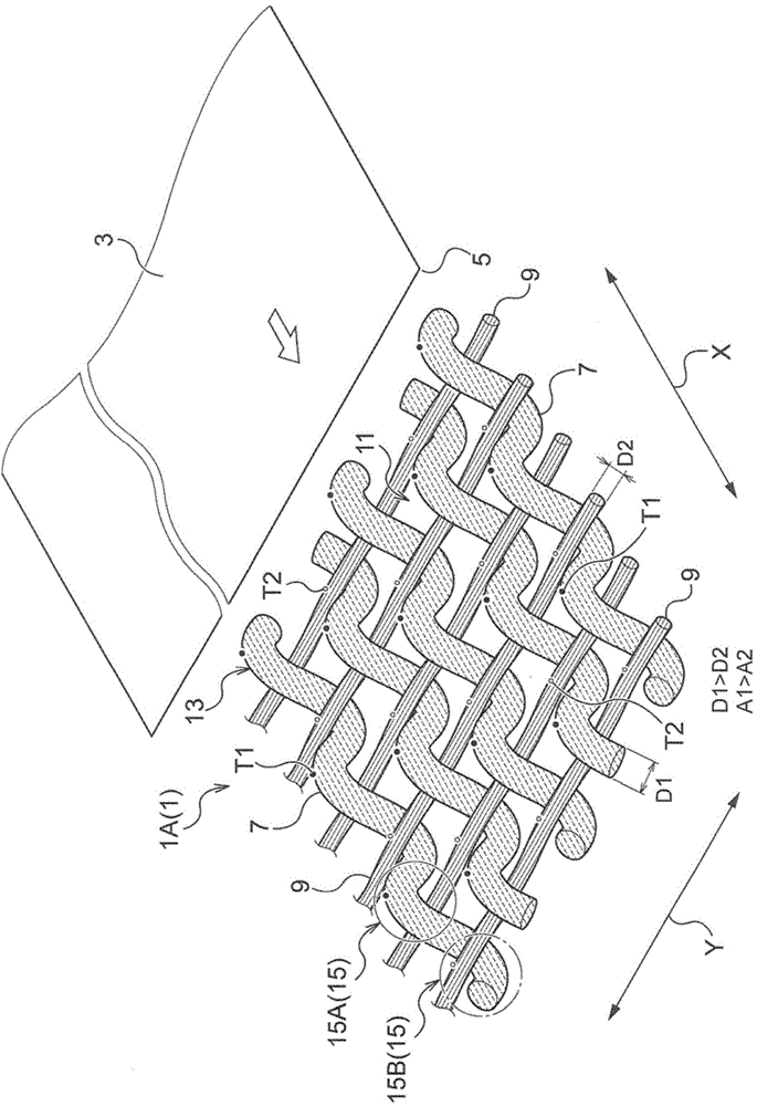
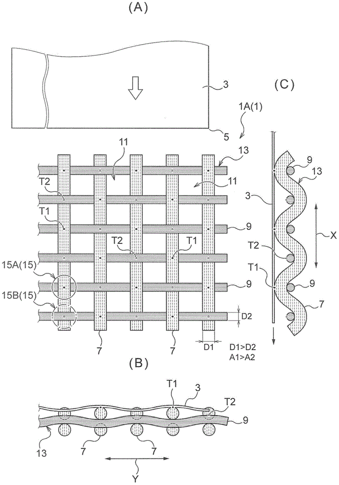
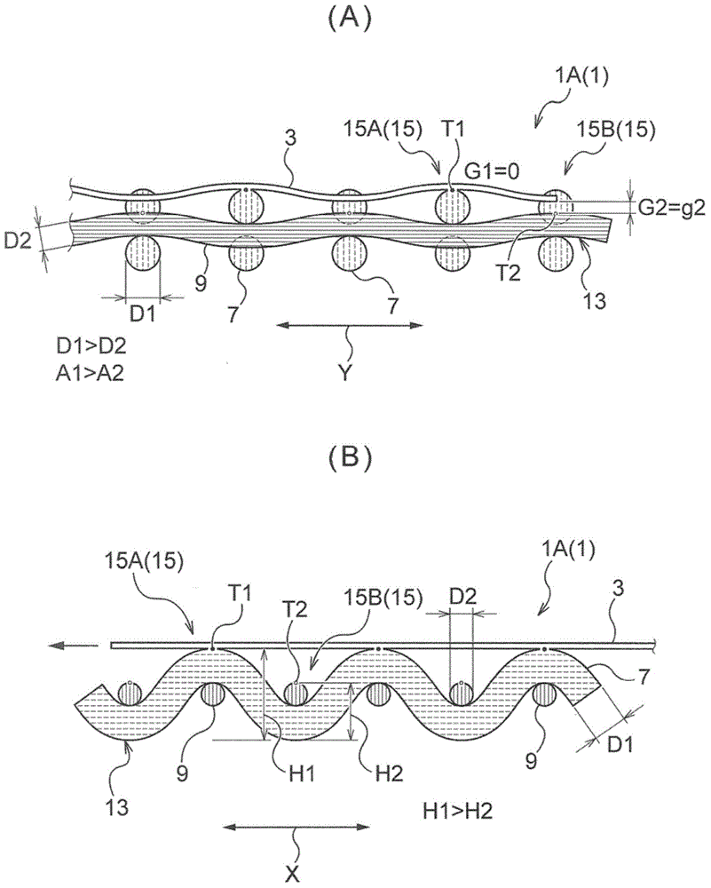
[0049] The mesh body 1 of the present invention is formed by weaving the first wires 7 arranged along the first direction X and the second wires 9 arranged along the second direction Y intersecting the first direction X in a different manner. mesh structure13.
[0050] In addition, it is characterized in that the cross-sectional area A1 of the first wire 7 at the intersection 15 where the first wire 7 intersects the second wire 9 is set to be larger than the cross-sectional area A2 of the second wire 9 at the intersection 15. .
[0051] In addition, in the mesh body 1A according to Embodiment 1, the wire diameter D1 of the first wire 7 is set to be larger than the cross-sectional area A2 of the second wire 9 in order to make the cross-sectional area A1 of the first wire 7 larger than the cross-sectional area A2 of the second wire 9. 2 The wire diameter D2 of the wire 9.
[0052] In a...
Embodiment approach 2
[0064] Embodiment 2 (refer to Figure 4 , Figure 5 as well as Figure 7 B, C type in)
[0065] In the mesh body 1B according to Embodiment 2, as a mode of making the cross-sectional area A1 of the first wires 7 larger than the cross-sectional area A2 of the second wires 9, the first wires 7 and the second wires 9 intersect at the intersecting parts. The 15 first wires 7 are used as a bundle, and the second wires 9 are used as a bundle of one or less than the first wires 7 to form the mesh structure 13 .
[0066] In addition, in Figure 4 , Figure 5 as well as Figure 7 In the type B in the diagram, the wire diameter D1 of the first wire rod 7 and the wire diameter D2 of the second wire rod 9 are set to the same wire diameter, and two first wire rods 7 in a bundle are used and only A 2nd wire rod 9 way.
[0067] In the case of mesh body 1B using such a method, such as Figure 7 As shown in the B type, although the wire diameters D1 and D2 of the first wire rod 7 and t...
Embodiment approach 3
[0074] Embodiment 3 (refer to Image 6 as well as Figure 7Type D in
[0075] The mesh body 1C according to Embodiment 3 is based on the premise that the cross-sectional area A1 of the first wire rod 7 is larger than the cross-sectional area A2 of the second wire rod 9, and further sets the interval P1 between adjacent first wire rods 7 to be smaller than The interval P2 between the adjacent second wires 9 .
[0076] In addition, in Image 6 as well as Figure 7 In the D type, as in Embodiment 1, by making the wire diameter D1 of the first wire rod 7 larger than the wire diameter D2 of the second wire rod 9, the wire diameters of the first wire rod 7 and the second wire rod 9 are made larger. D1 and D2 are set to be D1>D2, and accordingly, the cross-sectional areas A1 and A2 of the first wire rod 7 and the second wire rod 9 are set to be A1>A2. Furthermore, in the present embodiment, the interval P1 between the adjacent first wires 7 and the interval P2 between the adjace...
PUM
| Property | Measurement | Unit |
|---|---|---|
| diameter | aaaaa | aaaaa |
| diameter | aaaaa | aaaaa |
Abstract
Description
Claims
Application Information
 - R&D
- Intellectual Property
- Life Sciences
- Materials
- Tech Scout
- Unparalleled Data Quality
- Higher Quality Content
- 60% Fewer Hallucinations
Browse by: Latest US Patents, China's latest patents, Technical Efficacy Thesaurus, Application Domain, Technology Topic, Popular Technical Reports.
© 2025 PatSnap. All rights reserved.Legal|Privacy policy|Modern Slavery Act Transparency Statement|Sitemap|About US| Contact US: help@patsnap.com