Electrical Junction Box

A technology for electrical junction boxes and electronic components, which is applied in the direction of electrical components, etc., and can solve the problems of increased impedance value of contact parts, reduced contact area, and reduced reliability of connection between fuse 6 and terminal metal parts 4, etc.

Active Publication Date: 2015-08-26
YAZAKI CORP
View PDF5 Cites 5 Cited by
  • Summary
  • Abstract
  • Description
  • Claims
  • Application Information

AI Technical Summary

Problems solved by technology

In the case where the fuse 6 is inclined in this way, there may be a problem that the contact area between the terminal portion 62a and the terminal metal fitting 4 decreases and the resistance value of the contact portion increases, or that the connection between the fuse 6 and the terminal metal fitting 4 Reduced reliability

Method used


Image

  • Electrical Junction Box
  • Electrical Junction Box
  • Electrical Junction Box

Examples


Embodiment Construction

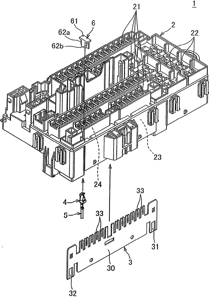
[0045] refer to Figure 1-7 An "electric junction box" according to one embodiment of the present invention will be described. figure 1 The illustrated electrical junction box 1 is an electrical junction box mounted on an automobile and mainly performs power distribution.

[0046]This electrical junction box 1 includes: a frame 2 made of synthetic resin; a plurality of components mounted on the frame 2 ; and a top cover made of synthetic resin mounted on the upper surface side of the frame 2 . In addition, the plurality of components mounted on the frame 2 are electronic components such as fuses and relays, electric wires, bus bars, and the like.

[0047] figure 1 Reference numeral 6 in is a fuse (equivalent to "electronic component" in the claims). This fuse 6 has: a case 61 ; a pair of terminal portions 62 a , 62 b exposed outside the case 61 ; and a fusible body accommodated in the case 61 . figure 1 The reference numeral 5 in is an electric wire, and the reference n...


PUM


Abstract

An electrical junction box provided by the present invention also can keep the connection state of an electronic part and a terminal metal member well even being used in an high temperature environment. The electrical junction box (1) is equipped with a frame (2), and the frame (2) is equipped with a fuse installing part (21) in which a fuse (6) is installed, and a terminal metal member installing part (24) in which the terminal metal member (4) connected with the fuse (6) electrically is installed. A pair of opposite surfaces (25) which extend parallelly with each other, a pair of inclined surfaces (26) extending towards the lower surface side of the frame (2) form the pair of opposite surfaces (25) respectively and tilting towards the directions separated from each other along with advancing from the upper surface side of the frame (2) to the lower surface side. A part of an embedding part (43) of the terminal metal member (4) is positioned between the pair of opposite surfaces (25), and the rest parts are positioned between the inclined surfaces (26).

Description

technical field [0001] The present invention relates to an electrical junction box mounted on an automobile and mainly performing power distribution. Background technique [0002] There are electrical junction boxes mounted on automobiles of various configurations, for example, there are such as Figure 9 , 10 An electrical junction box having a structure like the illustrated electrical junction box 301 has a frame 302 made of synthetic resin, and the frame 302 is provided with a fuse mounting portion 321, a terminal metal fitting mounting portion 324, and a bus bar mounting portion 323 (refer to Patent Document 1). [0003] The fuse mounting portion 321 is a portion where the fuse 6 is mounted, and is provided on the upper surface side of the frame 302 . A plurality of fuse mounting parts 321 are provided along one direction. The fuse 6 has a pair of terminal portions 62a, 62b. [0004] The terminal metal mounting portion 324 is a portion where the terminal metal 4 elec...

Claims


Application Information

Patent Timeline
Patent Type & Authority Applications(China)
IPC IPC(8): H02G3/16
Inventor 后藤裕一朗牧野匡宏佐滕润
Owner YAZAKI CORP
Why Eureka
Try Eureka