
Real-time prediction method of tool wear in hard rock tunnel boring machine cutter head tunneling system

A technology for tunnel boring machine and tunnel excavation, which is applied in tunnels, earth-moving drilling, instruments, etc., can solve the problem of not being able to effectively reflect the real-time estimation of the tool wear of the hard rock TBM cutter head excavation system in real time, etc., so as to improve the excavation efficiency. The effect of optimizing the tunneling parameters

Inactive Publication Date: 2017-02-22
TIANJIN UNIV +1
View PDF5 Cites 0 Cited by
  • Summary
  • Abstract
  • Description
  • Claims
  • Application Information

AI Technical Summary

Problems solved by technology

[0003] The technical problem to be solved by the present invention is to provide a method for real-time estimation of tool wear in the cutter head tunneling system of a hard rock tunnel boring machine, which is based on the rock breaking mechanics process of the hob and utilizes the tunneling parameters automatically collected during the hard rock TBM construction process, The method of estimating the tool wear of the hard rock TBM cutter head tunneling system in real time overcomes the shortcomings of the existing technology that cannot effectively reflect the tool wear of the hard rock TBM cutter head tunneling system in real time and the real-time prediction of the need to replace a new tool

Method used


Image

  • Real-time prediction method of tool wear in hard rock tunnel boring machine cutter head tunneling system
  • Real-time prediction method of tool wear in hard rock tunnel boring machine cutter head tunneling system
  • Real-time prediction method of tool wear in hard rock tunnel boring machine cutter head tunneling system

Examples


Embodiment 1

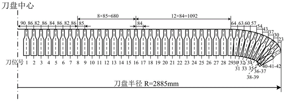
[0045] In the tunnel engineering of this embodiment, the structural parameters of the hard rock TBM used are as follows: cutterhead radius R=2.885m, 42 17in disc-shaped hobs are installed on the cutterhead, and the cutter installation radius on each cutter station is shown above figure 1 shown in the example described. The project is constructed under mixed granite geological conditions, and the detailed steps for estimating the wear and replacement of TBM cutterhead tools are given as follows:

[0046] The first step is to determine the change law of the energy consumption of the cutterhead tunneling system in the direction of cutterhead rotation with the energy consumption of the tunneling direction during the tunneling process of hard rock TBM:

[0047] The energy in the rotation direction of the hard rock TBM cutter head tunneling system has the following theoretical relationship with the energy in the tunneling direction:

[0048] E. r '=a·E p 0.67324 (1)

[0049] I...


PUM


Abstract

The invention discloses a method for real-time estimation of the tool abrasion condition of a cutter head tunneling system of a hard rock tunnel boring machine (TBM), and relates to tunneling equipment construction. The method comprises the following steps: determining the change rule of energy consumption of the cutter head tunneling system in the cutter head rotation direction in the tunneling process of the hard rock TBM along with the energy consumption in the tunneling direction, determining the tool abrasion energy consumption value of the cutter head tunneling system of the hard rock TBM, determining the accumulative consumed tool abrasion energy consumption value of the cutter head tunneling system of the hard rock TBM, determining the relation of the total tool abrasion energy consumption of the cutter head tunneling system of the hard rock TBM and the total tool abrasion size of the cutter head of the hard rock TBM, judging the abrasion conditions of tools on different mounting positions of the cutter head of the hard rock TBM to determine the tools needed to be replaced, and finally realizing real-time estimation of the tool abrasion replacement of the cutter head system of the hard rock TBM. Through the adoption of the method, the defects in the prior art that the tool abrasion condition of the cutter head tunneling system of the hard rock TBM as well as real-time estimation of new to-be-replaced tools cannot be effectively reflected in real time are overcome.

Description

technical field [0001] The technical scheme of the invention relates to the construction technology of tunnel excavation equipment, in particular to a method for real-time estimation of tool wear of a cutter head excavation system of a hard rock tunnel boring machine. Background technique [0002] Hard rock tunnel boring machine (hereinafter referred to as hard rock TBM) is a large-scale high-tech construction equipment specially used for excavating rock tunnels and underground passages. The disk hob of the hard rock TBM cutter head tunneling system has become the most numerous and most critical tunneling tool on the hard rock TBM cutter head due to its good rock breaking effect. During the construction process, the high-strength and high-hardness rock makes the tool wear problem of the hard rock TBM cutter head tunneling system very serious. In some projects, the cost and time spent on tool repair and replacement of the hard rock TBM cutter head tunneling system are close ...

Claims


Application Information

Patent Timeline
Patent Type & Authority Patents(China)
IPC IPC(8): E21D9/10
CPCE21D9/10G16Z99/00
Inventor 王立辉亢一澜张茜侯振德蔡宗熙曲传咏仇巍
Owner TIANJIN UNIV
Learn More