


Quick Research
Generate reliable direction feasibility study reports for your R&D in just a few steps.

Technical Q&A
Discover and master advanced knowledge NOW. Basics, ideas, possibilities, all at once.

Find Solutions
As an expert in R&D theories, this can generate solutions to your technical problems instantly.

Evaluate Feasibility
Analyze your overall solution with one click, know your potential R&D risks in advance.

Monitor Landscape
Get weekly tech updates, stay abreast of the latest tech innovations and key insights.
A low-permeability and high-water-cut oil field potential difference oil and water collection process
A low-permeability, water-collecting technology, applied in grease/oily/floating matter removal devices, liquid separation, chemical instruments and methods, etc., can solve the problems of high operating costs and difficult processing, save costs and reduce processing load , the effect of saving operating costs
- Summary
- Abstract
- Description
- Claims
- Application Information
AI Technical Summary
Problems solved by technology
Method used
Image

Examples
Embodiment 1
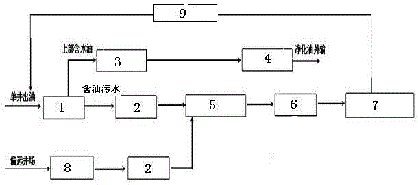
[0022] In order to overcome the problems in the prior art that oil and water are pulled together at the well site, the operating cost is high and the follow-up treatment is difficult, this embodiment provides a method such as figure 1 The shown low-permeability and high-water-cut oilfield potential differential oil and water collection process includes the following steps:
[0023] 1) Oil collection: the oil produced from a single well is preliminarily settled in the dirty oil tank 1, and the water-containing oil in the upper part after the preliminary settlement is transported to the nearest combined station 4 by the handling device 3 after purification and treatment.
[0024] 2) Water collection: Drain the oily sewage in the lower part of the single well after preliminary settlement into the low-level water tank, and then flow the oily sewage in the low-level water tank into the water collection station 5 through the water collection pipeline 2 connection.
[0025] 3) Produc...
Embodiment 2
[0030] On the basis of Example 1, the water collection system makes full use of the terrain height difference. The water collection station 5 is set at the place where 3-5 single well water collection pipelines 2 are concentrated. Different from the conventional oil collection process, according to the oil Due to the characteristics of high water cut in the area, more water and less oil, water collection pipelines and stations are set up instead of oil collection pipelines and stations; the reinjection station 7 is set at the center of the oil area.
[0031] In the above step 2) during the water collection process, in some remote and low-lying well sites, the oily sewage in the low-level water tank cannot flow into the water collection station 5 by itself, and the booster device 8 can be used to temporarily pressurize and then pass through the water collection pipeline 2 sent to the water collection station, and the booster 8 is a skid-mounted booster (comprising a water tank, ...
PUM
 Abstract
Description
Claims
Application Information
 - R&D Engineer
- R&D Manager
- IP Professional
- Industry Leading Data Capabilities
- Powerful AI technology
- Patent DNA Extraction
Browse by: Latest US Patents, China's latest patents, Technical Efficacy Thesaurus, Application Domain, Technology Topic, Popular Technical Reports.
© 2024 PatSnap. All rights reserved.Legal|Privacy policy|Modern Slavery Act Transparency Statement|Sitemap|About US| Contact US: help@patsnap.com