Method for adjusting a parking brake in a vehicle

A technology of parking brake and controller, applied in the direction of brake, brake type, axial brake, etc., can solve the problem of wrong value of clamping force, current drop, brake motor voltage disturbance, etc.

Active Publication Date: 2019-05-14
ROBERT BOSCH GMBH
View PDF8 Cites 0 Cited by
  • Summary
  • Abstract
  • Description
  • Claims
  • Application Information

AI Technical Summary

Problems solved by technology

If a further load is switched on after starting the brake motor, this can cause voltage disturbances and current drops in the brake motor, which in turn can lead to incorrect values ​​for the clamping force to be ascertained

Method used


Image

  • Method for adjusting a parking brake in a vehicle
  • Method for adjusting a parking brake in a vehicle
  • Method for adjusting a parking brake in a vehicle

Examples


Embodiment Construction

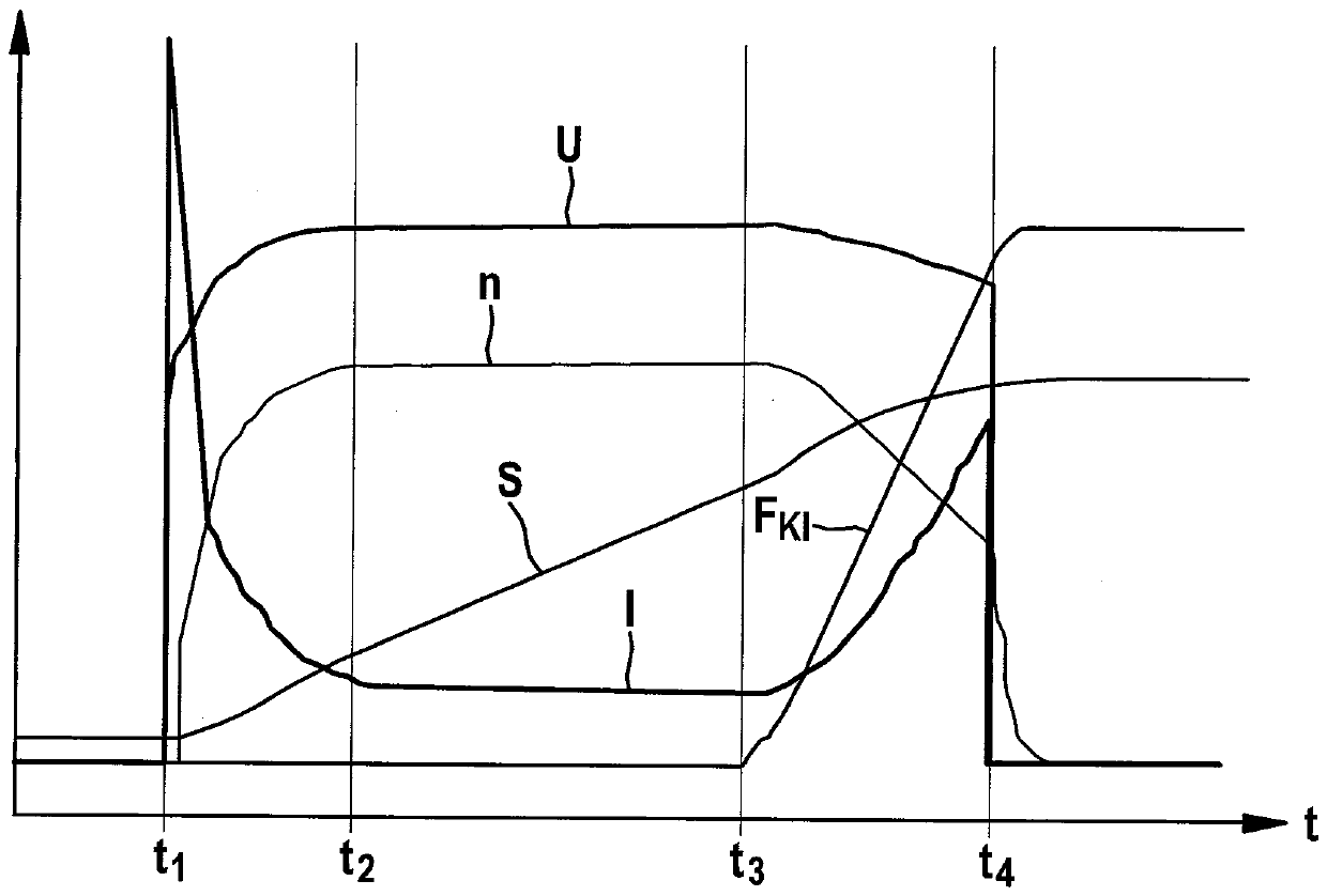
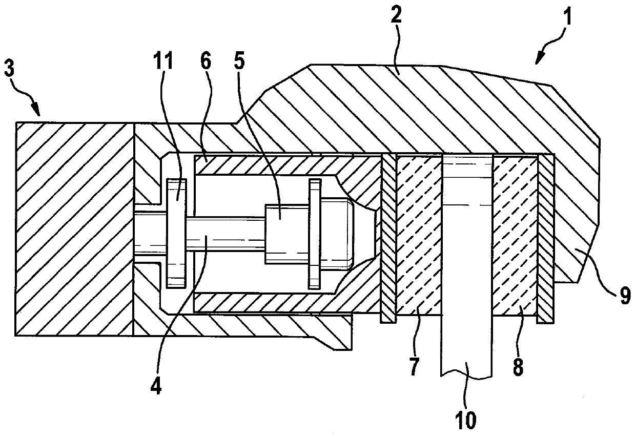
[0025] exist figure 1 shows an electromechanical parking brake 1 for immobilizing the vehicle in a stationary state. The parking brake 1 comprises a brake caliper 2 with a caliper 9 which engages a brake disc 10 . As an actuator, the parking brake 1 has an electric motor serving as a brake motor 3 , which drives a spindle 4 in rotation, on which a spindle nut configured as a spindle nut is rotatably supported. The spindle member 5. As the main shaft 4 rotates, the main shaft member 5 is adjusted in the axial direction. The spindle member 5 moves inside a brake piston 6 which is the base for a brake lining 7 which is guided by the brake piston 6 towards the brake disc. 10 squeezes. On the opposite side of the brake disk 10 there is a further brake lining 8 which is fixedly held on the clamp 9 .

[0026] Inside the brake piston 6, the spindle member 5 is able to move axially forwards in the direction of the brake disc 10 during a rotational movement of the spindle 4, or vic...


PUM


Abstract

The invention relates to a method for adjusting a parking brake comprising an electromechanical braking device with a brake motor for generating an electromechanical clamping In this method, the standard deviation is determined from the current curve of the brake motor based on the measured current values, and a correction current is determined for the standard deviation exceeding a limit value, which serves as a reference The basis for calculation of the motor parameters of the brake motor for ascertaining the clamping force.

Description

technical field [0001] The invention relates to a method for adjusting a parking brake in a vehicle according to the preamble of claim 1 . Background technique [0002] DE 10 2006 052 810 A1 describes a method for estimating the clamping force generated by a brake motor in a parking brake of a motor vehicle. The brake motor moves a brake piston axially towards the brake disc, wherein the brake piston is the seat of the brake lining. The clamping force generated here is determined from a system of differential equations describing the electrical and mechanical properties of the brake motor, taking into account the current, the supply voltage of the brake motor and the speed of the motor. characteristic. [0003] Like a series of other electrical loads, the brake motor is supplied with current in the motor vehicle via the on-board electrical system. If a further load is switched on after starting the brake motor, this can cause voltage disturbances and current drops in the ...

Claims


Application Information

Patent Timeline
Patent Type & Authority Patents(China)
IPC IPC(8): B60T13/74G01L5/22
CPCB60T13/741G01L5/22B60T13/588B60T13/662F16D55/226F16D65/18F16D2121/04F16D2121/14B60T8/171B60T8/172
Inventor U.苏泽克
Owner ROBERT BOSCH GMBH
Why Eureka
Try Eureka