
Power switch variable frequency driving mechanism and switch cabinet

A technology of variable frequency drive and power switch, applied in contact drive mechanism, electric switch, power device inside the switch, etc., can solve the problem of easy arcing of switching appliances, achieve rapid separation, ensure safety performance, and avoid arcing. Effect

Inactive Publication Date: 2015-08-12
孟越峰 +1
View PDF5 Cites 0 Cited by
  • Summary
  • Abstract
  • Description
  • Claims
  • Application Information

AI Technical Summary

Problems solved by technology

[0004] One of the objectives of the present invention is to provide a power switch variable frequency drive mechanism to solve the problem of easy arcing in switching appliances in the prior art

Method used


Image

  • Power switch variable frequency driving mechanism and switch cabinet
  • Power switch variable frequency driving mechanism and switch cabinet
  • Power switch variable frequency driving mechanism and switch cabinet

Examples


Embodiment Construction

[0014] In the following detailed description, numerous specific details are set forth in order to provide a thorough understanding of the present invention. However, it will be understood by those skilled in the art that the present invention may be practiced without these specific details. In other instances, well-known methods, procedures, components and circuits have not been described in detail so as not to obscure the present invention.

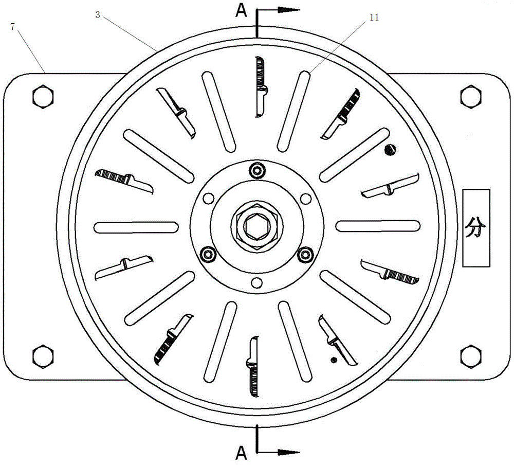
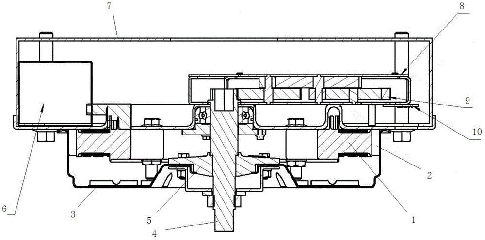
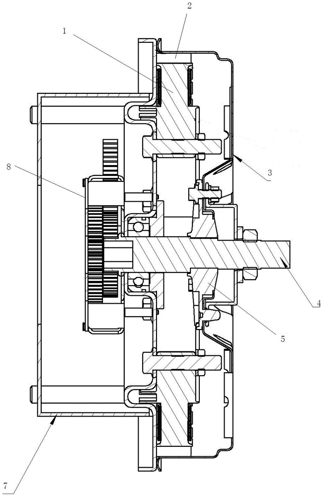
[0015] Such as Figure 1-3 As shown, a power switch variable frequency drive mechanism is disclosed, including: a turntable 3 driven to rotate by a stator 1 and a rotor 2; a rotating shaft 4 that runs through the center of the turntable 3 and is fixedly connected to the turntable 3; One end of the switch is used to directly or indirectly drive the switch in the switch cabinet to open or close. Wherein, the rotor 2 is a permanent magnet.

[0016] The invention can realize the fast separation between the switch contacts by rotating the ...


PUM


Abstract

The invention provides a power switch variable frequency driving mechanism and a switch cabinet. The power switch variable frequency driving mechanism comprises a turntable which is driven by a stator and a rotor to rotate and a rotating shaft which goes through the center of the turntable and is fixedly connected to the turntable. One end of the rotating shaft is used for directly or indirectly driving the switch in the switch cabinet to be disconnected or connected. According to the power switch variable frequency driving mechanism, the separation of the switch cabinet is driven through rotation, the rapid separation of a switch contact can be realized, a large distance is made between contacts instantly, thus the generation of an arc is avoided, and the safety performance of a switch electrical appliance is ensured.

Description

technical field [0001] The invention belongs to the technical field of power switches, in particular to a power switch variable frequency drive mechanism. Background technique [0002] Switch cabinets are important electrical equipment in power plants and substations. However, when the switching device disconnects the current, if the circuit voltage is not lower than 10-20 volts and the current is not lower than 80-100 mA, an arc will be generated between the contacts of the electrical device, which is a very serious safety hazard. [0003] This kind of problem is mainly due to the fact that when the switch contacts are separated, the distance between the contacts is very small and the electric field strength is very high. When it is higher than the critical value, the electrons on the surface of the cathode will be pulled out by the electric field force to form a space between the contacts. The free electrons form an arc. Contents of the invention [0004] One of the ob...

Claims


Application Information

Patent Timeline
IPC IPC(8): H01H3/26H01H3/40H01H9/52
CPCH01H3/26H01H3/40H01H9/52H01H2003/266
Inventor 孟越峰陶卫兴韩萍周正
Owner 孟越峰
Learn More