
Microscopic simulation modeling method used in carbon fiber composite material removing process

A simulation modeling and composite material technology, applied in special data processing applications, instruments, electrical digital data processing, etc., can solve problems such as providing reference for cutting process research, matching, and simulation analysis results are difficult to process, etc.

Active Publication Date: 2015-08-12
DALIAN UNIV OF TECH
View PDF3 Cites 20 Cited by
  • Summary
  • Abstract
  • Description
  • Claims
  • Application Information

AI Technical Summary

Problems solved by technology

Most of the existing methods use finite element modeling to discuss the material removal process from the mesoscopic point of view, but there are also shortcomings: the interface phase and the appropriate material model are not integrated into the mesoscopic simulation model at the same time. , so it cannot simulate the mesoscopic removal process of carbon fiber composite material interface cracking, fiber matrix damage, etc.
Such as G.VenuGopalaRao etc., the article "Micro-mechanical modeling of machining of FRP composites-Cutting force analysis" published in "Composites Science and Technology" magazine No. 67, 2007, page 579-593, establishes multiple roots, different directions Mesoscopic model, since there is no defined material failure criterion, it can only simulate interface cracking, and cannot realize the material removal process
Therefore, it is difficult for the simulation analysis results to match the actual cutting process, let alone provide a reference for the research of the cutting process.

Method used


Image

  • Microscopic simulation modeling method used in carbon fiber composite material removing process
  • Microscopic simulation modeling method used in carbon fiber composite material removing process
  • Microscopic simulation modeling method used in carbon fiber composite material removing process

Examples


Embodiment Construction

[0035] The specific implementation of the present invention will be described in detail below in conjunction with the technical scheme and accompanying drawings, and the present invention will be described by taking the 0° carbon fiber reinforced epoxy resin-based composite unidirectional board as an example. The finite element simulation calculation software is ABAQUS, and the specific steps of the simulation method are as follows:

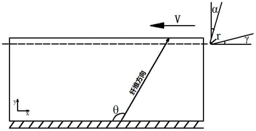
[0036] (1) Create a geometric model of the tool and the workpiece. The workpiece type is a two-dimensional deformable body, and the workpiece size is 1mm×0.6mm. The tool is set as an analytical rigid body, the rake angle α of the tool is 20°; the back angle γ of the tool is 10°, and the radius r of the tool edge circle is 10 μm, such as figure 1 shown.

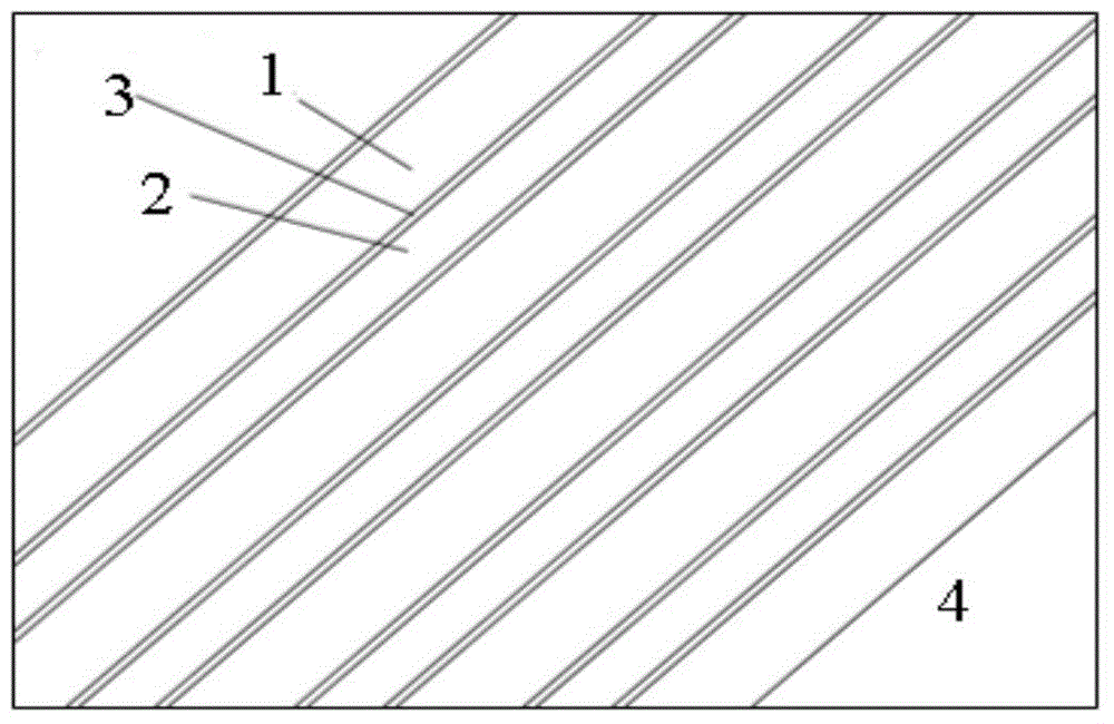
[0037] (2) Since mesoscopic modeling is a multiphase modeling method, there are fiber phase 1, matrix phase 2, interface phase 3 and equivalent homogeneous phase 4, such as figure 2 shown. I...


PUM

PropertyMeasurementUnit
shear modulusaaaaaaaaaa
densityaaaaaaaaaa
tensile strengthaaaaaaaaaa

Abstract

The invention discloses a microscopic simulation modeling method used in the carbon fiber composite material removing process, belongs to the field of finite element simulation cutting and relates to a microscopic simulation modeling method used in the material removing process during cutting and processing of carbon fiber reinforced epoxy resin matrix composite materials. According to the simulation modeling method, two-dimensional microscopic modeling for cutting the carbon fiber composite materials is performed through finite element software, and a multi-phase modeling method is adopted, wherein multiple phases comprise a fiber phase, a matrix phase, an interface phase and an equivalent homogeneous phase; different material models are adopted for the phases with different components, and four two-dimensional microscopic cutting models at typical fiber angles are established for the material models on the basis of the constitutive relation of materials and the damage starting and evolving norm. In the whole process from microscopic layer damage to macroscopic cutting, lots of human cost, experiment cost and economic cost are saved, and the problem that online observation of an experimental method is difficult is avoided.

Description

technical field [0001] The invention belongs to the field of finite element simulation cutting, and relates to a mesocosmic simulation modeling method for the material removal process in the cutting process of carbon fiber reinforced epoxy resin-based composite materials. Background technique [0002] Carbon fiber composite material is an advanced composite material, which is widely used in aviation, aerospace, automobile and other machinery manufacturing fields due to its excellent mechanical properties. However, due to the complexity of the composition of carbon fiber composites, there is no unified theory for the research on its removal process, and different damages will occur during the processing, which will seriously affect the service life of composite components. Therefore, the material removal process of carbon fiber composites is still the focus of research in the field of composite materials processing. [0003] At present, the research on its material removal p...

Claims


Application Information

Patent Timeline
Patent Type & Authority Applications(China)
IPC IPC(8): G06F17/50
Inventor 贾振元高汉卿王福吉张博宇殷俊伟
Owner DALIAN UNIV OF TECH
Learn More