
Power device temperature detection system

A technology of electric equipment and detection system, applied in the field of electric equipment temperature detection system, can solve the problems of reducing equipment service life, power failure experiment, equipment destructiveness, etc.

Inactive Publication Date: 2015-08-12
STATE GRID CORP OF CHINA +2
View PDF2 Cites 1 Cited by
  • Summary
  • Abstract
  • Description
  • Claims
  • Application Information

AI Technical Summary

Problems solved by technology

The traditional insulation preventive test has played a certain role in preventing the occurrence of power equipment accidents, but its fatal weakness is the need for power failure experiments, and some items are destructive to the equipment, reducing the service life of the equipment

Method used


Image

  • Power device temperature detection system

Examples


Embodiment

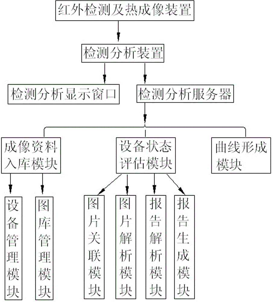
[0010] Embodiment: power equipment temperature detection system, such as figure 1 As shown, it includes an infrared detection and thermal imaging device installed on each electrical equipment, a detection and analysis device that receives information from the infrared detection and thermal imaging device, and a detection and analysis display window and a detection and analysis server are set on the detection and analysis device.

[0011] The detection and analysis server is provided with an imaging data storage module, a curve forming module and an equipment status evaluation module, and its working steps are: a. The information of infrared detection and thermal imaging devices is stored in The detection and analysis server; b. The curve forming module forms a graph of infrared detection and thermal imaging information, and displays it in the detection and analysis display window; or, the equipment status evaluation module receives the imaging data in the storage module The re...


PUM


Abstract

The invention relates to a power device temperature detection system. The power device temperature detection system is characterized in that infrared detection and thermal imaging devices are disposed on various power devices, and detection analysis devices are used for receiving the information of the infrared detection and thermal imaging devices, and are provided with detection analysis display windows and detection analysis servers. The power device temperature detection system is advantageous in that the monitoring of the surface temperatures of the power devices and the distribution thereof can be realized; by deepening the infrared detection technology, the non-contact on-line infrared detection and thermal imaging technology can be adopted to monitor the operation state of the power devices, and therefore the current states of the power devices can be known timely, the fault causes can be found effectively, and the future states of the devices can be predicted.

Description

technical field [0001] The invention relates to a temperature detection system for electric equipment. Background technique [0002] The power system is the lifeblood of the national economy, and whether the power equipment can work normally is directly related to the safe operation of the power system. With the increasing reliability requirements of power equipment. In order to ensure the reliable and stable operation of power equipment, it is necessary to fully rely on scientific and technological progress and improve the level of technical supervision. The traditional insulation preventive test has played a certain role in preventing the occurrence of power equipment accidents, but its fatal weakness is the need for power failure experiments, and some items are destructive to the equipment, reducing the service life of the equipment. Contents of the invention [0003] The purpose of the present invention is to solve the above-mentioned problems existing in the prior a...

Claims


Application Information

Patent Timeline
IPC IPC(8): G01J5/00
Inventor 田晖叶军辉何涛毛宾一管钧斌
Owner STATE GRID CORP OF CHINA
Learn More