
Hydrofoil

A technology of hydrofoil and rear wing, applied in the field of hydrofoil, can solve the problems of large size, achieve wear-resistant connection, facilitate air transportation, and be easy to manufacture

Inactive Publication Date: 2015-08-12
ELLERGON ANTRIEBSTECHN
View PDF4 Cites 11 Cited by
  • Summary
  • Abstract
  • Description
  • Claims
  • Application Information

AI Technical Summary

Problems solved by technology

[0003] Conventional hydrofoils, such as published publication number US2005 / 0266746 A1, only have limited suitability for different purposes, and their size is bulky

Method used


Image

  • Hydrofoil
  • Hydrofoil
  • Hydrofoil

Examples


Embodiment Construction

[0036] Below in conjunction with accompanying drawing, the present invention is described in further detail with specific embodiment, as follows:

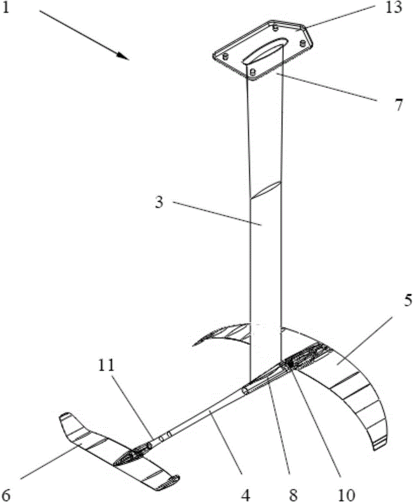
[0037] figure 1 In the illustrated embodiment, one is secured to a surfboard (board) 2 suitable for kitesurfing and wakeboarding (see Figure 7 ) on hydrofoil 1.

[0038] Said hydrofoil 1 comprises keel ribs 3 , also sometimes referred to as masts or struts, connecting rods 4 , ie fuselage, front wings 5 ​​, and rear wings 6 . These parts are connected to each other through standard interfaces, therefore, these parts can be replaced individually. The result is a modular system that can be flexibly adapted to different purposes.

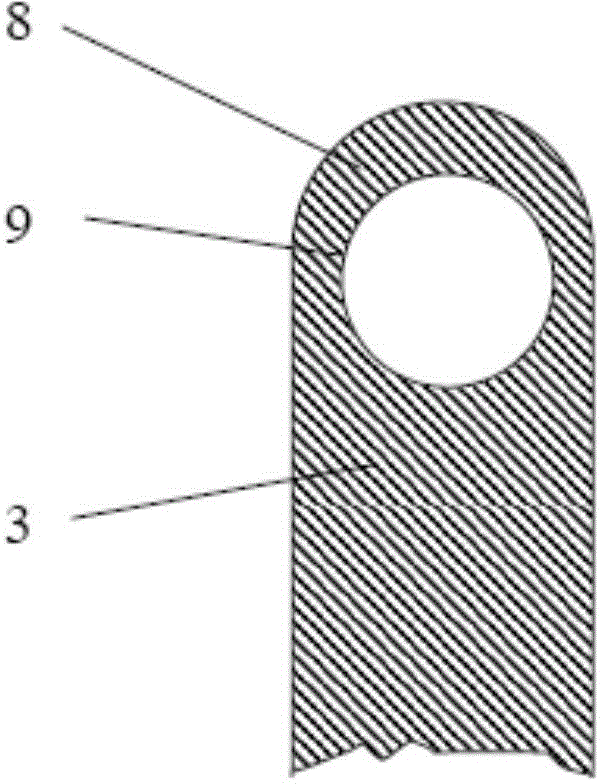
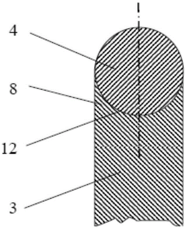
[0039] The keel rib 3 has a first end 7 for fixing to a board 2 and a second end 8 for connecting a connecting rod 4 . The height of the keel rib 3 is preferably about 700 to 1000 mm, the thickness is about 10 to 30 mm, and the length in the moving direction is about 80 to 150 mm. The keel ribs 3 are ...


PUM

PropertyMeasurementUnit
Diameteraaaaaaaaaa
Lengthaaaaaaaaaa

Abstract

A hydrofoil (1), particularly suitable for kite surfing and jet skiing, comprises a keel fin (3) having a first end portion (7) for fastening to a board, and a front wing (5) and a rear wing (6) which are arranged one behind the other in the travel direction and are connected to a second end portion (8) of the keel fin (3). A connecting rod (4) is situated on the second end portion (8) of the keel fin (3) and detachably connects the wings (5, 6) to the keel fin (3). A plate (20) is situated on an outer side of the keel fin (3) and on an outer side of at least one of the wings (5, 6), and via detachable fastening means (21) is braced to the connecting rod (4) so as to detachably fasten at least one of the wings (5, 6) to the keel fin (3).

Description

technical field [0001] The invention relates to a hydrofoil comprising a keel rib having a first end for fixing a board, and a front wing and a rear wing arranged one behind the other in the direction of motion, the front wing and the rear wing being connected to the second end of the keel rib. Background technique [0002] This type of hydrofoil lifts the board out of the water to reduce flow resistance during kitesurfing or wakeboarding, with only a portion of the keel ribs and wings remaining submerged during the above process. [0003] Conventional hydrofoils, such as published publication number US2005 / 0266746 A1, only have limited suitability for different purposes and their size is bulky. In addition, the connection areas between the keel ribs and the wings are subject to strong stresses due to the forces generated during operation. Contents of the invention [0004] The object of the present invention is to provide an improved hydrofoil with respect to the above ...

Claims


Application Information

Patent Timeline
IPC IPC(8): B63B35/79B63B35/81B63B35/85B63B1/24
CPCB63B1/26B63B1/248B63B35/7923B63B35/7953B63B1/242B63B35/731B63B32/66B63B32/64
Inventor 科尼利斯·盖斯林格
Owner ELLERGON ANTRIEBSTECHN
Learn More