New girder for sawing machine

A technology for sawing machines and beams and slabs, which is applied to sawing machine devices, large fixed members, metal sawing equipment, etc., can solve the problems of unfavorable hard material cutting, insufficient rigidity of beams, etc., and achieve the effect of sufficient rigidity

Active Publication Date: 2017-05-24
浙江仁工机械有限公司
View PDF5 Cites 0 Cited by
  • Summary
  • Abstract
  • Description
  • Claims
  • Application Information

AI Technical Summary

Problems solved by technology

[0003] The purpose of the present invention is to provide a new beam of the sawing machine, which solves the problem that in the prior art, the column sleeve of the sawing machine and the beam plate are connected by screws.

Method used


Image

  • New girder for sawing machine
  • New girder for sawing machine
  • New girder for sawing machine

Examples


Embodiment Construction

[0013] The present invention will be described in detail below in conjunction with the accompanying drawings and specific embodiments.

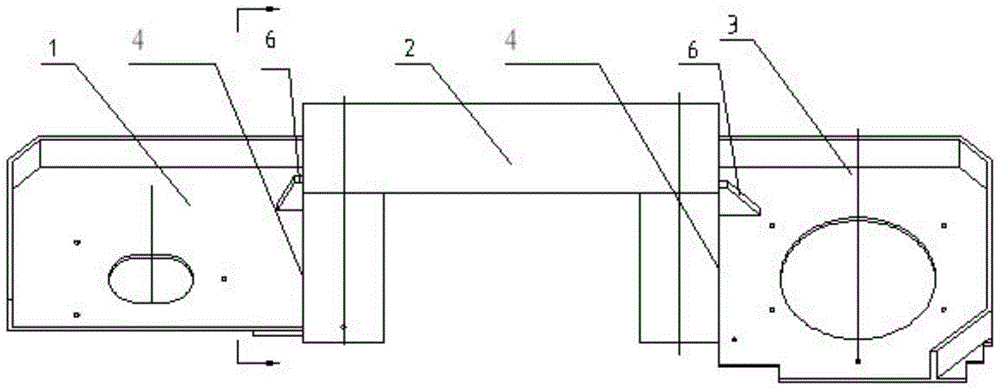
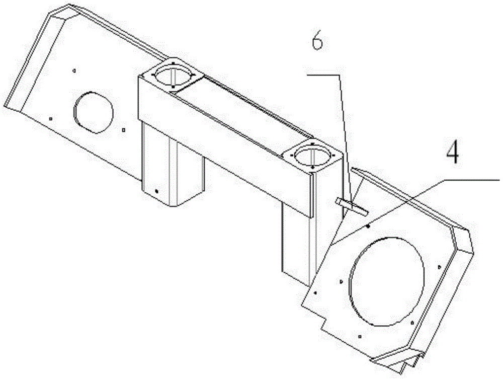
[0014] Such as figure 1 and image 3 , Figure 4 , The new beam of the sawing machine includes a column cover 2 and a beam plate. The beam plate includes a left beam plate 1 and a right beam plate 3. It is characterized in that the left beam plate 1 and the right beam plate 3 are directly welded on both sides of the column cover 2 respectively.

[0015] The left beam plate 1 and the right beam plate 3 are directly welded on the column sleeve 2 through a welding mold to form an integral beam, so that the sawing machine beam has more rigidity, less deformation and is more suitable for sawing hard materials.

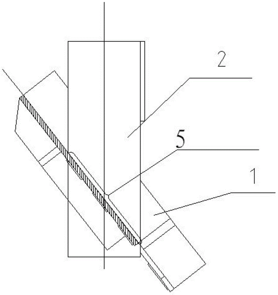
[0016] The weld 4 between the column sleeve 2 and the beam slab is an ultra-long weld 5, and the ultra-long weld 5 extends linearly from one end of the intersection of the column sleeve 2 and the beam slab to the other end of the interse...


PUM


Abstract

The invention discloses a novel cross beam of a sawing machine. The novel cross beam comprises a column sleeve and beam plates. The beam plates comprise the left beam plate and the right beam plate. The left beam plate and the right beam plate are directly welded to the two sides of the column sleeve respectively. An ultra-long welded position exists between the column sleeve and each beam plate, and extends in a straight line from one crossed end of the column sleeve and corresponding beam plate to the other crossed end of the column sleeve and the corresponding beam plate. According to the novel cross beam of the sawing machine, the left beam plate and the right beam plate are directly welded to the two sides of the column sleeve to form a whole, and the traditional sawing machine cross beam screw connection way is changed, so that the cross beam of the sawing machine is higher in rigidity, small in deformation and better applicable to hard material sawing.

Description

technical field [0001] The invention relates to a sawing machine girder. Background technique [0002] The traditional sawing machine column sleeve and the beam plate are connected by screws. This connection method is insufficient for the rigidity of the beam, which is not conducive to the cutting of hard materials. Contents of the invention [0003] The purpose of the present invention is to provide a new beam of the sawing machine, which solves the problem that the traditional sawing machine column sleeve and the beam plate are connected by screws, which is not conducive to the cutting of hard materials due to insufficient rigidity of the beam. [0004] The technical solution adopted in the present invention is: the new beam of the sawing machine includes a column cover and a beam plate, the beam plate includes a left beam plate and a right beam plate, and the left beam plate and the right beam plate are directly welded on both sides of the column cover respectively. ...

Claims


Application Information

Patent Timeline
Patent Type & Authority Patents(China)
IPC IPC(8): B23Q1/01
CPCB23D47/02B23D51/02B23D55/02B23Q1/015
Inventor 吕伟仁吕设强汪群妃吕伟治陈文龙
Owner 浙江仁工机械有限公司
Why Eureka
Try Eureka