
Fiber bragg grating sensor for measuring contact stress at rolling interface

A fiber grating and contact stress technology, which is applied in the field of strip rolling, can solve problems such as marks left by rolling strips, disturbance of friction conditions, and low stiffness of pressure measuring needles.

Inactive Publication Date: 2015-08-05
WUHAN UNIV OF SCI & TECH
View PDF5 Cites 0 Cited by
  • Summary
  • Abstract
  • Description
  • Claims
  • Application Information

AI Technical Summary

Problems solved by technology

[0004] The first is a direct needle-shaped sensor, which mainly uses two pressure measuring needles with a small cross-sectional size to directly measure the normal pressure and shear stress. The main limiting factor of this sensor is that the pressure measuring needles are in direct contact with the strip, which will Leaves an impression on the strip, and in order to better measure the strain accurately, the stiffness at the pressure measuring pin is relatively low, which will cause higher elastic deformation than the surrounding rolls during rolling, which will affect the rolling interface. Frictional conditions produce certain disturbances;
[0005] The second type is a sensor measuring unit pressure and friction with a size larger than the contact arc length. Viewed from the side, it is frame-type with two columns, each of which is equipped with two sensors for measuring vertical and horizontal stress. Strain gauge, according to the position change of the sensor entering the work roll gap and the four measurement signals of the strain gauge, the unit pressure and friction force at each position on the contact arc can be determined; this sensor overcomes the local over-deformation of the above-mentioned pressure measuring needle problem, but since the sensor is also in contact with the strip, it will also leave an impression on the rolled strip;
[0007] At present, the roll sensor is only realized by pasting the strain gauge on the edge of the roll on the experimental rolling mill, while on the industrial rolling mill, the roll is wider than the plate, and the edge of the roll is not in contact with the plate

Method used


Image

  • Fiber bragg grating sensor for measuring contact stress at rolling interface
  • Fiber bragg grating sensor for measuring contact stress at rolling interface
  • Fiber bragg grating sensor for measuring contact stress at rolling interface

Examples


Embodiment Construction

[0025] The following will clearly and completely describe the technical solutions in the embodiments of the present invention in combination with the embodiments of the present invention and the accompanying drawings. Obviously, the described embodiments are only some of the embodiments of the present invention, not all of them. Based on the embodiments of the present invention, all other embodiments obtained by persons of ordinary skill in the art without making creative efforts belong to the protection scope of the present invention.

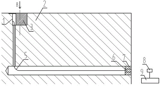
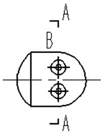
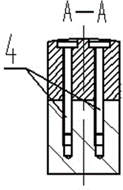
[0026] see Figure 1-Figure 4 , in an embodiment of the present invention, a fiber grating sensor for measuring contact stress at a rolling interface, comprising a fiber grating rosette 1, a roll 2, a plug 3, a screw 4, an optical cable 5, a fiber collimator A6, and a collimator Fixed sleeve 7, fiber collimator B8, three-dimensional micro-displacement adjustment table 9. There is a stepped hole above the rolling area on the surface of the rol...


PUM


Abstract

The invention discloses a fiber bragg grating sensor for measuring the contact stress at a rolling interface. The fiber bragg grating sensor comprises a roller. The surface of the roller is provided with a stepped hole. One face, perpendicular to the axis direction of the roller, of the stepped hole is milled flat and milled with a slot. A fiber bragg grating strain rosette is adhered to the slot. A plug is located at the upper portion of the stepped hole. The stepped hole is provided internally with a slender hole to the axis of the roller. The axis at an operating side of the roller is provided with a hole communicating with the slender hole. The fiber bragg grating strain rosette is connected a fiber collimator A through an optical cable. The fiber collimator A is fixed at the opening of the hole of the axis at the operating side of the roller through a collimator fixing sleeve. A fiber collimator B is mounted on a three-dimensional micro displacement adjustment table. The fiber collimator B is further connected with a fiber bragg grating wavelength demodulator. The fiber bragg grating wavelength demodulator is connected with a computer. According to the invention, through indirect measurement of normal stress and shearing stress at the rolling interface, impression can be avoided on a plate and tape and no disturbances will be generated to friction and lubrication at the rolling interface.

Description

technical field [0001] The invention relates to the field of strip rolling, in particular to an optical fiber grating sensor for measuring contact stress at a rolling interface. Background technique [0002] During strip rolling, two rolls are used as tools to reduce the thickness of the rolled piece. The current rolling trends are: higher rolling speeds, greater reductions, harder steel grades and thinner strips. In order to ensure better product quality, especially in terms of thickness, flatness and defect-free surfaces, knowledge of friction and lubrication in the roll gap becomes critical, requiring knowledge of the normal stress at the contact point between the strip and the roll and shear stress. Measuring the contact stress at the roll gap to obtain the optimum parameters of rolling speed and lubrication has always been an important aspect in the field of rolling. [0003] At present, there are mainly three sensors for measuring the contact stress of the rolli...

Claims


Application Information

Patent Timeline
Patent Type & Authority Applications(China)
IPC IPC(8): G01L1/24
Inventor 王志刚肖进辉郭永兴王涛
Owner WUHAN UNIV OF SCI & TECH
Learn More