Staged vacuum preloading soft soil ground reinforcing technology

A technology of vacuum preloading method and soft soil foundation, which is used in the drainage treatment of soft soil foundation and silt. The staged vacuum preloading method can solve the blockage of drainage board, affect the degree of vacuum and reduce soil reinforcement. effects, etc.

Active Publication Date: 2015-08-05
WENZHOU UNIVERSITY
View PDF1 Cites 1 Cited by
  • Summary
  • Abstract
  • Description
  • Claims
  • Application Information

AI Technical Summary

Problems solved by technology

On the one hand, due to the lateral deformation of the drainage board, when the pore water is discharged along the longitudinal direction of the drainage board and passes through the bend, the resistance of the drainage board will increase, and the soil particles in the pore water will be deposited here to form a silt cluster phenomenon. Causes the blockage of the drainage board, thereby reducing the drainage efficiency of the deep drainage board and reducing the reinforcement effect of the soil;
In this way, when the pore water seeps, it often carries soil particles with small particle sizes, which are directly discharged with the pore water, causing the loss of soil particles, or gathering around the drainage board to form a silt layer, which affects the transmission of the vacuum degree and reduces the vacuum. stress utilization
[0005] The existing vacuum preloading technology often uses a new type of anti-silting drainage board, which mainly adjusts the pore size of the drainage board filter membrane to prevent sludge clogging, and does not consider the vertical drainage board caused by the radial contraction of the soil. factors such as lateral deformation
Therefore, although changing the pore size of the filter membrane of the vertical drainage plate can alleviate the phenomenon of silt clumping to a certain extent, it has no effect on alleviating the bending of the vertical drainage plate under the lateral stress of the soil and the silt clogging at the bend. not obvious

Method used


Image

  • Staged vacuum preloading soft soil ground reinforcing technology
  • Staged vacuum preloading soft soil ground reinforcing technology
  • Staged vacuum preloading soft soil ground reinforcing technology

Examples


Embodiment Construction

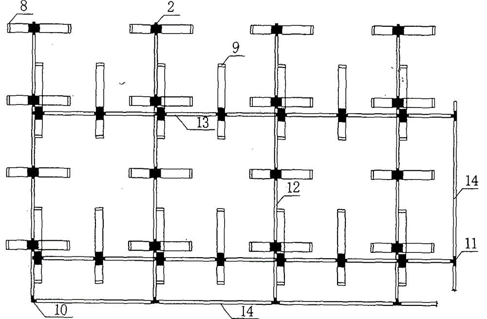
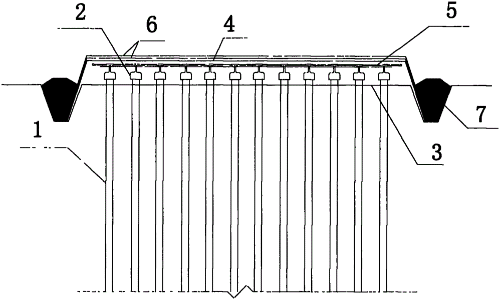
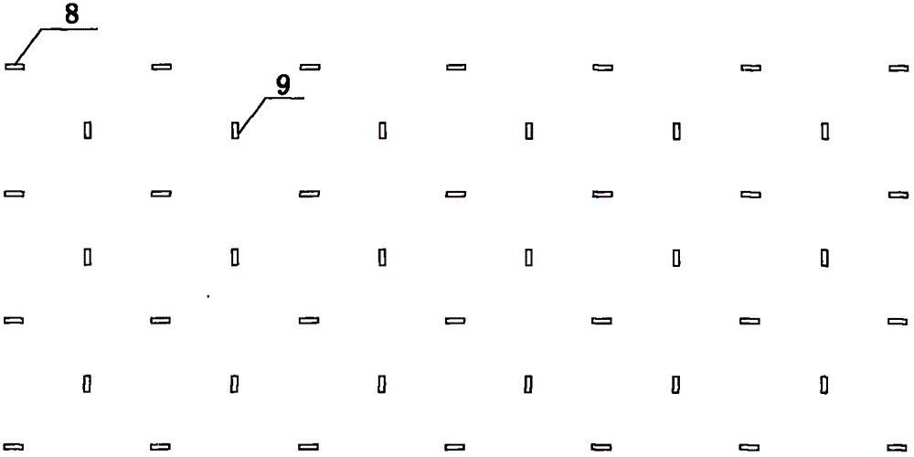
[0013] During specific implementation, a layer of woven cloth is laid on the soft ground that needs to be treated, the vertical drainage boards of the pretreatment vacuum system and the reprocessing vacuum system are positioned, and then the vertical drainage boards are installed. According to engineering experience, the spacing between drainage boards is 0.8-1.2m. At the same time, considering that the radius of the reverse filter layer of the drainage board is about 0.5m, the distance between the drainage boards is set to 0.8m. Connect the vertical drainage board of the pretreatment vacuum system with its horizontal drainage branch pipe, and connect the vertical drainage board of the retreatment vacuum system with its horizontal drainage branch pipe, and connect the horizontal drainage branch pipes of the two vacuum systems with their horizontal drainage main pipes respectively. To connect, lay a layer of geotextile, lay a layer of sealing film, respectively connect the hori...


PUM


Abstract

The invention relates to a staged vacuum preloading soft soil ground reinforcement and treatment method, which mainly comprises a pretreatment stage and a retreatment stage. According to the technology, vertical draining plates are pretreated for carrying out preliminary reinforcing treatment on soil bodies, and retreatment is carried out after a soft soil layer is transformed into a soil ground with certain bearing capability from a soft plastic-flow plastic state and is stable in radial shrinkage, so that the following situations can be avoided, and the situations include: the vertical draining plates are bent due to uniform radial shrinkage of shallow-layer soil bodies generated during vacuum preloading, so that the effect of transferring vacuum to deep-layer draining plates and the draining effect of the deep-layer draining plates; in the later period of vacuum preloading, soil particles with smaller particle size flow and are gathered around the draining plates to form a clogging layer, so that the draining plates are blocked.

Description

technical field [0001] The invention belongs to the field of soft soil foundation treatment, and more specifically relates to a method for treating soft soil foundation by a staged vacuum preloading method, which is suitable for drainage treatment of soft soil foundation and silt. Background technique [0002] A large amount of soft soil is distributed along the river and coastal areas of our country. Today, with the increasingly tight construction land, how to deal with these soft soils to meet the needs of engineering construction has always been a technical problem. In particular, the treatment of dredging fill in the southeast coastal areas has become a key technology for ports, transportation and urban construction in coastal areas. [0003] Since the 1980s, my country began to propose and apply the method of vacuum preloading to treat soft soil foundations. Through continuous improvement and innovation in engineering practice, the theory and technology of vacuum preloa...

Claims


Application Information

Patent Timeline
Patent Type & Authority Applications(China)
IPC IPC(8): E02D3/10
CPCE02D3/10
Inventor 蔡袁强王鹏符洪涛王军金亚伟丁光亚胡秀青谷川郭林宓炜
Owner WENZHOU UNIVERSITY
Why Eureka
Try Eureka