
Screw supplying device

A screw machine and chassis technology, applied in metal processing, metal processing equipment, manufacturing tools, etc., can solve the problem of not being able to automatically screen out defective products

Active Publication Date: 2015-07-29
DONGGUAN OKATA ELECTRONICS & TECH
View PDF4 Cites 12 Cited by
  • Summary
  • Abstract
  • Description
  • Claims
  • Application Information

AI Technical Summary

Problems solved by technology

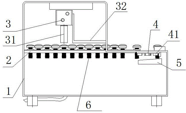
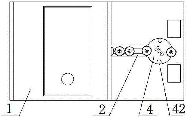
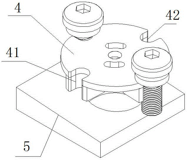
[0003] The technical problem to be solved by the present invention is to provide a screw designed with a flattening cylinder and a pressing needle to flatten the screw, so as to prevent the screw washer from being stuck on the screw rod and cause the screw to be skewed during the transmission process, so that the screw cap and the screw Gaskets can be jointed tightly; through the setting of a limited height frame, if the screw gasket and the screw cap are not transported in a state of joint and close contact during the transmission process, the screw will not be able to be conveyed through the limited height frame, so as to screen out defective products ; It is also provided with a protective block, which is used in conjunction with the turntable, and the protective block and the turntable are respectively provided with limit holes of the same diameter, which can position the screw and prevent it from being skewed when it is placed; it is also provided with a spacer. When the screw moves in a circular motion, it plays the role of jacking, so that the screw can be separated from the turntable after being raised, which is convenient for the manipulator to pick up the screw. It has high precision, high efficiency of screw supply, and high degree of intelligence. Now, the time for each screw transmission is ≤0.5S , The good product rate reaches 99%, which solves the problems of traditional manual feeding, skewed screw transmission process, high defective product rate, and cannot automatically screen out defective products. It is easy to use, simple in structure, low in cost, and meets the high requirements of industrialization development. screw machine

Method used


Image

  • Screw supplying device
  • Screw supplying device
  • Screw supplying device

Examples


Embodiment Construction

[0014] In this example, if Figure 1 to Figure 5 As shown, a screw machine of the present invention includes a chassis 1, a transmission guide rail 2 arranged transversely in the middle of the chassis 1, a screw 6 transported on the transmission guide rail 2, and a height-limiting frame 32 arranged above the transmission guide rail 2 , and the flattening cylinder 3 arranged at the center of the top inner side of the cabinet 1, and the pressing pin 31 arranged under the flattening cylinder 3, and the turntable 4 arranged at the right end of the transmission guide rail 2, and the limit position arranged at the edge of the turntable 4 Hole 42, and the protective block 41 that is arranged on the circumference of the turntable 4, and the limiting hole 42 that is arranged on the protective block 41, and the riser block 5 that is arranged under the turntable 4; the limiting hole 42 is provided with two Above, the shape of each of the limiting holes 42 is set in a semicircle, and the ...


PUM


Abstract

The invention discloses a screw supplying device. The screw supplying device comprises a machine box, a conveying guide rail, a screw, a height limiting frame, a flattening air cylinder, a pressing needle, a turn plate, a limiting hole, a protecting block, limiting holes and a heightening block. The designed flattening air cylinder and the pressing needle can be used for flattening the screw so as to prevent a screw gasket from being blocked on a screw rod so as to cause deflection of the screw during a conveying process, and a screw cap and the screw gasket are enabled to be tightly jointed and conveyed; by arranging the height limiting frame, defective products can be screened out; the protecting block is arranged and matched with the turn plate in use; the protecting block and the turn plate are respectively provided with limiting holes which are the same in diameter to locate the screw, so that deflection is prevented when the screw is arranged; a heightening plate is also arranged for upwards-pushing the screw during circumferential motion of the screw, so that the screw can be separated from the turn plate after being conveyed and heightened; convenience is provided for a mechanical arm to suck the screw; the screw supplying device is high in accuracy, high in screw supplying efficiency, high in intelligent level, simple in structure, low in cost and capable of satisfying high requirements of industrial development.

Description

technical field [0001] The invention relates to a screw feeder. Background technique [0002] When the traditional screw machine conveys and feeds the material, it mainly uses manual operation to feed the material, and the labor cost is high. When the traditional screw conveyor belt conveys the screw with the washer, the screw is easily stuck on the screw and the screw is stuck on the screw. Skew during the transmission process, so that when the screw is in place, the screw is skewed, causing the manipulator to absorb the screw due to unstable suction and easy to fall off, the accuracy is poor, and the screw supply efficiency is low. The time it takes to transmit a screw each time is 1S or more. Therefore, in view of the deficiencies of the above-mentioned technical problems in the feeding of the traditional screw machine, the applicant has developed a design with a flattening cylinder and a pressing needle to flatten the screw, preventing the screw gasket from being stuck ...

Claims


Application Information

Patent Timeline
IPC IPC(8): B23P19/06
CPCB23P19/001B23P19/06
Inventor 吴水鱼
Owner DONGGUAN OKATA ELECTRONICS & TECH
Learn More