
Power supply systems

一种供电系统、电源的技术,应用在电磁波系统、电路、电感器等方向

Active Publication Date: 2015-07-22
HUNZA HLDG
View PDF7 Cites 1 Cited by
  • Summary
  • Abstract
  • Description
  • Claims
  • Application Information

AI Technical Summary

Problems solved by technology

Also, the connection of new equipment is likely to require professional installation to ensure that the connection of new equipment meets the sealing requirements of the system

Method used


Image

  • Power supply systems
  • Power supply systems
  • Power supply systems

Examples


Embodiment Construction

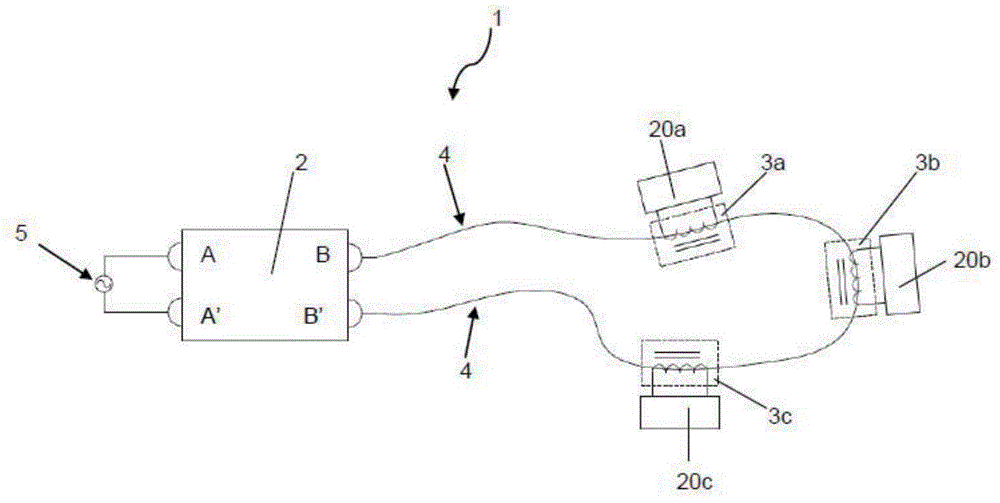
[0097] figure 1 A power supply system is shown, which is generally designated with reference numeral 1 . The power supply system 1 comprises a power source 2 connected to a transmission line 4 via connection points B, B'. The power source 2 is configured to provide a constant alternating current through the transmission line 4 . Pickups 3 a , 3 b and 3 c are inductively coupled to the transmission line 4 . It will be appreciated that additional couplers may inductively couple to the transmission line 4 or conversely any one of the couplers 3 a , 3 b or 3 c may remove inductive coupling from the transmission line 4 . The power supply 2 is supplied to the main power supply 5 through connections A, A'.

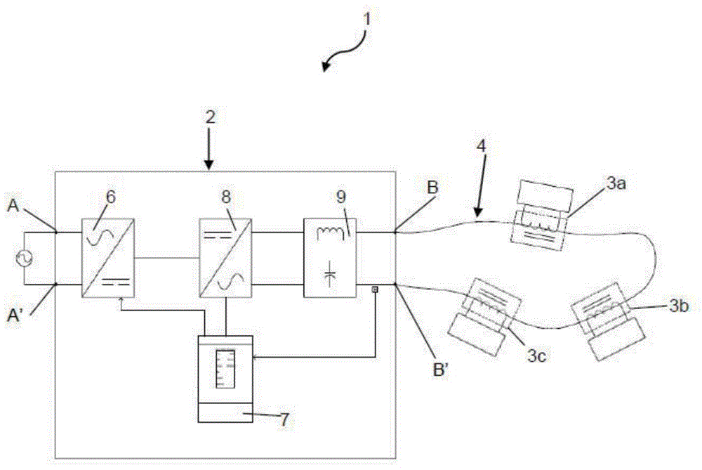
[0098] figure 2 shown in figure 1 The schematic diagram of the power supply 2 of the power supply system 1 is shown in . The power supply 2 comprises input terminals A, A' configured for connection to a power supply. figure 1 , the source of electrical energy is show...


PUM


Abstract

A power supply system including: a power supply configured to provide a constant AC current; a power transmission line connected to the power supply to form a closed circuit; and at least one pickup configured to accept and slidingly engage with the power transmission line such that the pickup completely encircles a portion of the power transmission line threaded through the pickup, and to inductively couple to the power transmission line, wherein the at least one pickup can be positioned at any point along the length of the power transmission line by sliding it along the power transmission line.

Description

[0001] This application is based on the provisional application specification filed on New Zealand Patent Application No. NZ603646, the entire contents of which are hereby incorporated by reference. technical field [0002] The invention relates to improvements in power supply systems with associated transmission lines. The invention is of particular advantage in situations where one or more circuits can be added to or removed from the power supply system. Background technique [0003] For the sake of clarity, the power supply system of the present invention will be described with reference to only a few installations, rather than a detailed and exhaustive list of possible installations. In this respect, the power supply system of the present invention should not be seen as limited to the installations described below. [0004] Lighting systems designed to operate in hazardous or harsh conditions (for example, outdoors, in variable environments or underwater), usually custo...

Claims


Application Information

Patent Timeline
Patent Type & Authority Applications(China)
IPC IPC(8): H02J17/00H05B41/24H01F38/14
CPCH02J5/005H01F38/14H05B37/0263H05B41/24H05B47/185H02J50/10Y10T29/49021H01F27/24H02J3/00H02J5/00H02J7/02
Inventor 安德鲁·威廉·坎宁安
Owner HUNZA HLDG
Learn More