
RTK (real time kinematic)-based piling positioning auxiliary system and utilization method thereof

A positioning assistance and technical technology, applied in the direction of satellite radio beacon positioning system, radio wave measurement system, measurement device, etc., can solve the problems of inability to obtain pile position deviation in real time, insufficient night-time visibility conditions, and exceeding specification requirements, etc. , to achieve the effect of sharing construction data and results, improving intuitiveness, and ensuring construction quality

Active Publication Date: 2015-07-22
SHENZHEN BEIDOUYUN INFORMATION TECH CO LTD +1
View PDF3 Cites 14 Cited by
  • Summary
  • Abstract
  • Description
  • Claims
  • Application Information

AI Technical Summary

Problems solved by technology

When using measuring instruments to deploy pile positions, it will also be difficult to operate due to insufficient visibility conditions at night
Stakeout by RTK measuring instruments requires on-site input of coordinates. The pile machine will cause the displacement of the pile position during the movement process, and it is impossible to obtain the displacement status of the pile position during the construction process in real time, which will easily cause the deviation error to exceed the specification after the pile construction is completed. Require

Method used


Image

  • RTK (real time kinematic)-based piling positioning auxiliary system and utilization method thereof
  • RTK (real time kinematic)-based piling positioning auxiliary system and utilization method thereof
  • RTK (real time kinematic)-based piling positioning auxiliary system and utilization method thereof

Examples


Embodiment Construction

[0028] The specific embodiments of the present invention will be described in further detail below in conjunction with the accompanying drawings, but this does not constitute any limitation to the present invention.

[0029] Such as figure 1 , 2 , as shown in 3:

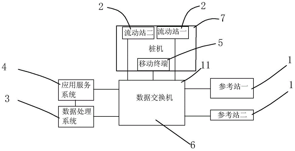
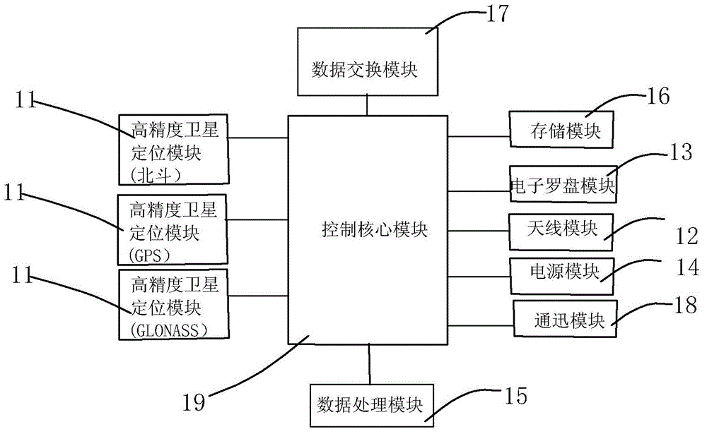
[0030] An RTK technology-based piling positioning assistance system, characterized in that: the system includes a reference station 1 based on RTK technology, a mobile station 2, a data processing system 3, an application service system 4, a mobile terminal 5, and a data transfer machine 6 , pile driver 7, described reference station 1, rover station 2, mobile terminal 5 are interconnected with data processing system 3, application service system 4 through data exchange 6, and described reference station 1 is located at the target project relatively fixed already Coordinate points, the application service system 4 is installed on the mobile terminal 5, the mobile terminal 5 is set on the pile driver 7, and the mobi...


PUM


Abstract

The invention provides a RTK (real time kinematic)-based piling positioning auxiliary system and a utilization method thereof. The system comprises a RTK-based reference station, a mobile station, a data processing system, an application service system, a mobile terminal, a data switcher and a pile driver. The reference station, the mobile station and the mobile terminal are connected with the data processing system and the application service system through the data switcher. The reference station is arranged at a relatively fixed known coordinate point of a target project, the mobile terminal is provided with the application service system, the mobile station and the mobile terminal are arranged on the pile driver, and the mobile station can be also arranged at an independent point outside the pile driver. An operator of the pile driver can complete pile driver positioning (piling position determination) according to display or prompt of the application service system installed on the mobile terminal, and accordingly intermediate links in a positioning process can be reduced, and directness, convenience and accuracy in operation of piling position determination are improved. Furthermore, construction efficiency of the pile driver is improved, the problems of pay-off difficulty in night construction and the like are solved, and the RTK-based piling positioning auxiliary system has the advantages of simplicity in operation, accuracy in positioning, monitorability in construction and sharability of construction data and achievements.

Description

technical field [0001] The invention relates to a pile driving positioning auxiliary system, which is based on RTK technology and installed on various types of pile driver equipment to assist the pile driver to quickly and accurately complete pile position positioning. Background technique [0002] At present, during the construction of the pile machine, the placement of the pile needs to be done through general-purpose measuring instruments (including RTK measuring instruments), and at the same time, it needs the cooperation of multiple people. When the pile position is deployed by measuring instruments, it will also be difficult to operate due to insufficient visibility conditions at night. Stakeout through RTK measuring instruments requires on-site input of coordinates. The pile driver will cause the displacement of the pile position during the movement process, and it is impossible to obtain the displacement status of the pile position during the construction process in ...

Claims


Application Information

Patent Timeline
IPC IPC(8): G01S19/45
CPCG01S19/45
Inventor 李慧生赖光程刘熙平赵其华
Owner SHENZHEN BEIDOUYUN INFORMATION TECH CO LTD
Learn More