Endurance test device for temperature valve

A technology of durability test and temperature valve, which is applied in the direction of measuring devices, strength characteristics, instruments, etc., can solve the problems of slow heating and cooling speed of high and low temperature impact box, inconvenient observation of temperature valve action, high operating cost of high and low temperature impact box, etc., to achieve The effect of low cost, simple structure and convenient durability test

Inactive Publication Date: 2015-07-22
CHONGQING CHAOLI HI TECH
View PDF5 Cites 4 Cited by
  • Summary
  • Abstract
  • Description
  • Claims
  • Application Information

AI Technical Summary

Problems solved by technology

[0002] There is a temperature valve inside the oil cooler. When the oil temperature changes, the temperature valve will control the size of the valve according to the temperature change to adjust the work of the oil cooler. Therefore, whether the temperature valve works normally determines whether the oil cooler can work normally. Therefore, when designing the oil cooler, a durability test must be carried out on the temperature valve. The main function of this experiment is to observe whether the temperature valve of the oil cooler has any faults during the long-term operation. There is no special equipment for the experiment, and the high and low temperature impact box is generally used instead of the experiment, but there are the following problems: 1. The high and low temperature impact box is a sealed device, which is inconvenient to observe the action of the temperature valve; 2. The heating and cooling speed of the high and low temperature impact box is too high. 3. The structure of the high and low temperature impact box is complex and expensive; 4. The operating cost of the high and low temperature impact box is relatively high; therefore, we need to design a device specially used for the temperature valve durability test

Method used


Image

  • Endurance test device for temperature valve
  • Endurance test device for temperature valve

Examples


Embodiment 1

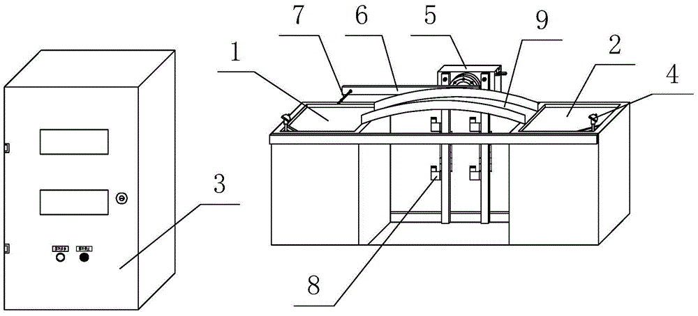
[0012] Embodiment 1: as figure 1 and figure 2 As shown, the present invention includes a high-temperature pool 1, a low-temperature pool 2 and an electrical control cabinet 3, a thermocouple 4 is respectively arranged outside the high-temperature pool 1 and the low-temperature pool 2, and a thermocouple 4 is arranged between the high-temperature pool 1 and the low-temperature pool 2. Rotary cylinder 5, said rotary cylinder 5 is located in the middle of the connection line between high temperature pool 1 and low temperature pool 2, said rotary cylinder 5 is provided with a rocker arm 6, one end of rocker arm 6 is connected with rotary cylinder 5, and the other end is provided with There is a fixed rod 7 for fixing the temperature valve. The fixed rod 7 is located on the side of the rocker arm 6 close to the high temperature pool 1 and the low temperature pool 2. The rotary cylinder 5 is provided with a solenoid valve 8 for controlling its work. The electric The control cabine...

Embodiment 2

[0013] Embodiment 2: Same as the above-mentioned embodiment 1, wherein an arched protective liquid tank 9 is connected between the above-mentioned high temperature pool 1 and low temperature pool 2, and the highest point of the protective liquid tank 9 is located at the high temperature pool 1 and the low temperature pool 2 The center plane of the connecting line.

[0014] During the use of the present invention, the temperature valve to be tested is first fixed on the fixed rod 7, and then the high-temperature pool 1 and the low-temperature pool 2 are electrically heated through the electric control cabinet 3 to make them reach the temperature required for the test, and then the temperature valve Put it into the high-temperature pool 1, and after a certain period of time, control the rocker arm 6 by rotating the cylinder 5, move the temperature valve to the low-temperature pool 2, and conduct a temperature change test. The arched protective liquid tank 9 is set in the middle, ...


PUM


Abstract

The invention discloses an endurance test device for a temperature valve. The endurance test comprises a high-temperature pool, a low-temperature pool and an electric control cabinet, wherein a thermocouple is respectively arranged out of the high-temperature pool and the low-temperature pool; a rotary air cylinder is arranged between the high-temperature pool and the low-temperature pool; a rocker is arranged on the rotary air cylinder, and one end of the rocker is connected with the rotary air cylinder while the other end of the rocker is provided with a fixing rod for fixing the temperature valve; the fixing rod is positioned on one side of the rocker close to the high-temperature pool and the low-temperature pool; the rotary air cylinder is provided with an electromagnetic valve for controlling the rotary air cylinder to work; the electric control cabinet is internally provided with a temperature controller which is respectively connected with the thermocouple and the electromagnetic valve through wires. The endurance test device disclosed by the invention is reasonable in design and simple in structure. By adopting two critical ambient temperatures simulating action of the temperature valve and by using electric heating as well as controlling at a constant temperature by using the temperature controller, the experimental requirements are achieved, so that the endurance test of the temperature valve is convenient and efficient, and the endurance test device is relatively high in reliability and low in cost and operating cost.

Description

technical field [0001] The invention belongs to the technical field of temperature valve detection in oil coolers, and in particular relates to a temperature valve durability test device. Background technique [0002] There is a temperature valve inside the oil cooler. When the oil temperature changes, the temperature valve will control the size of the valve according to the temperature change to adjust the work of the oil cooler. Therefore, whether the temperature valve works normally determines whether the oil cooler can work normally. Therefore, when designing the oil cooler, a durability test must be carried out on the temperature valve. The main function of this experiment is to observe whether the temperature valve of the oil cooler has any faults during the long-term operation. There is no special equipment for the experiment, and the high and low temperature impact box is generally used instead of the experiment, but there are the following problems: 1. The high and ...

Claims


Application Information

Patent Timeline
Patent Type & Authority Applications(China)
IPC IPC(8): G01N3/60
Inventor 孙波曾光荣李顺荣
Owner CHONGQING CHAOLI HI TECH
Why Eureka
Try Eureka