Connector assembly

A connector assembly, electrical connection technology, applied in the direction of vehicle connectors, connections, parts of connecting devices, etc., can solve problems such as deterioration of sealing performance, inconsistency in performing tight contact of sealing parts, etc.

Active Publication Date: 2015-07-15
YAZAKI CORP
View PDF7 Cites 2 Cited by
  • Summary
  • Abstract
  • Description
  • Claims
  • Application Information

AI Technical Summary

Problems solved by technology

With the sealing member attached in this state, when the housing is fitted to the mounting hole, tight contact of the sealing member with respect to the groove portion of the housing and the inner peripheral portion of the mounting hole is not uniformly performed in the circumferential direction , and thus, incurs the deterioration of the sealing performance

Method used


Image

  • Connector assembly
  • Connector assembly

Examples


Embodiment Construction

[0032] A connector assembly according to the present invention will be described below with reference to the accompanying drawings. The connector assembly according to the present invention is an interconnection member for electrically connecting (specifically, electrically connecting and separation). For example, a case can be assumed as a suitable example in which an inverter of a motor mounted on a vehicle such as an electric car driven using a motor, a hybrid car driven using both an engine and a motor is connected to a The electrical junction box (junction box) of the power supply unit that supplies power to the motor.

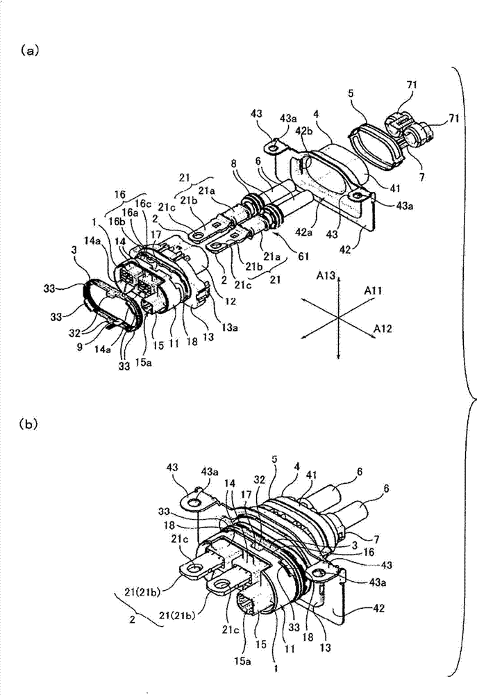
[0033] figure 1 (a) and 1(b) are diagrams showing the overall structure of a connector assembly according to an embodiment of the present invention, wherein, figure 1 (a) is a perspective view of a connector assembly disassembled into constituent parts, figure 1 (b) is shown assembled figure 1 A perspective view of the overall structure in the state ...


PUM


Abstract

A connector assembly is provided with: a housing (1) which holds an electrical wire-side terminal (2) and which is fitted in a mounting hole formed in the case of a counter-connection device; and a seal member (3) which is mounted in a groove (16) formed in the outer peripheral section (11) of the housing and which maintains the inside of the case in a liquid-tight condition. The seal member (3) has on the bent portions thereof protrusion-shaped sections (33) which are formed so as to protrude in the widthwise direction from an annularly continuing band-shaped peripheral edge. The groove (16) has recess-shaped sections (18) which are formed by recessing a groove wall (16b) such that the recess-shaped sections (18) correspond to the protrusion-shaped section (33). The protrusion-shaped sections (33) and the recess-shaped sections (18) engage with each other.

Description

technical field [0001] The present invention relates to a connector assembly for interconnecting terminals. Background technique [0002] Vehicles such as electric cars that run using a motor and hybrid cars that run using an engine and a motor are driven with electric power supplied to the motor from a power source mounted on the vehicle. For example, in a hybrid car, a motor and an inverter are connected to each other using wires such as motor cables. In addition, the inverter is connected to an electric junction box (junction box) provided in the power source, and thus, electric power is supplied from the power source to the motor. In this case, the inverter and the electrical junction box are connected to each other using a given connector part (connector assembly). [0003] As an example of the connector assembly as described above, there is known a connector assembly having a structure in which a mounting hole is formed in a casing of an inverter or an electric junct...

Claims


Application Information

Patent Timeline
Patent Type & Authority Applications(China)
IPC IPC(8): H01R13/52
CPCH01R13/5202H01R2201/26
Inventor 繁田祯典中山光一
Owner YAZAKI CORP
Why Eureka
Try Eureka