
Parameterized and automatic geometric correction method for multi-projector tiled display

A technology of splicing display and geometric correction, applied in image data processing, instruments, 3D modeling, etc., can solve the problems of complex system, long initial correction and re-correction time, low accuracy of correction results, etc., to achieve high calculation accuracy, avoid Effects of ambiguity and false positives, low resolution and field of view

Active Publication Date: 2015-07-15
BEIHANG UNIV
View PDF4 Cites 31 Cited by
  • Summary
  • Abstract
  • Description
  • Claims
  • Application Information

AI Technical Summary

Problems solved by technology

Most of the methods bypass the geometric model of the projector and the screen, and directly use the projected model screen to compare and adjust the benchmark on the projection screen. The time period is long, and the initial calibration and recalibration time is long.
[0007] 2. There is a lot of manual intervention in the offline calibration project
The calibration process relies on experience and is too subjective, so it is difficult to quantitatively evaluate the calibration results
[0008] 3. The system is too complicated, which increases the cost and reduces the reliability
Existing methods increase the complexity of the system by printing infrared references on the projection screen or directly installing reference points on the projection screen, and affect the final display effect of the projection system
[0009] 4. There are many limitations in automatic calibration, and the configuration is not flexible
Existing automatic correction methods require the camera to see all or most of the projection channel to be corrected, and automatic correction cannot be realized when the projection display system is located in a small space; Large screens either require more detailed subdivisions to increase the complexity of the calibration, or the resulting calibration results are not accurate

Method used


Image

  • Parameterized and automatic geometric correction method for multi-projector tiled display
  • Parameterized and automatic geometric correction method for multi-projector tiled display
  • Parameterized and automatic geometric correction method for multi-projector tiled display

Examples


Embodiment Construction

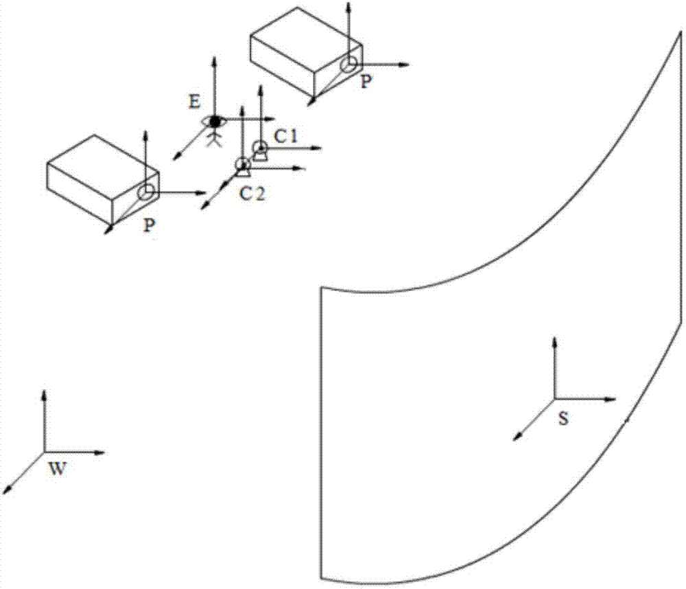
[0054] In the present invention, a camera pair (two cameras forming a stereo camera) and a camera are introduced as additional hardware needed in the parametric automatic correction process, which is realized through two parts of off-line geometric correction and real-time image correction, such as figure 1 shown.

[0055] Among them, the off-line correction is based on the method of stereo vision and projection system geometric modeling to obtain the geometric parameters of the multi-projection display system, including the internal and external parameters of the projector, the geometric parameters of the projection screen and the external parameters of the observer; the specific steps of the offline correction are:

[0056] Step 1. Perform geometric modeling on the multi-projection mosaic display system, such as figure 2 shown;

[0057] a. Define the world reference coordinate system W;

[0058] To perform geometric modeling on a multi-channel projection display system, i...


PUM


Abstract

The invention discloses a parameterized and automatic geometric correction method for multi-projector tiled display. The method comprises two parts, namely, off-line correction and real-time correction. The off-line correction comprises steps as follows: two stereo cameras acquire mode image sequences projected by respective projection channels, feature point information of the respective projection channels on screens is acquired through calculation from the acquired mode image sequences, and unknown parameters in geometric models in the projection screens as well as inner and outer parameters of respective projectors are calculated accordingly, position and posture information of an observer is acquired, and all the unknown parameters in geometric models in a projection system are acquired finally. The real-time correction comprises steps as follows: the acquired parameters are used as system configuration files, the system configuration files are loaded in real time, and a rendered multi-channel display image is a high-resolution image which is correct in perspective relation and free of edge mutation. The method has the advantages as follows: parameter calibration of the multi-projector display system can be finished automatically, and the requirement for the resolution and field angles of the cameras is lower.

Description

technical field [0001] The invention relates to a correction method for a multi-projection splicing display system, specifically, a parameterized automatic geometric correction method for multi-projection splicing display. Background technique [0002] Multi-projection splicing display technology is a technology that stitches and fuses the images projected by multiple projectors to achieve a seamless image with a larger size and higher resolution than a single display device. A display system using multi-projection splicing display technology is called a multi-projection splicing display system. The main elements of a multi-projection splicing display system include projectors, projection surfaces (projection screens) and observers. Even if there is no need for interaction, the viewer's information is very important and will determine the best viewing area for the display system. [0003] Multi-projection splicing display technology is a typical large-screen display techno...

Claims


Application Information

Patent Timeline
IPC IPC(8): G06T7/00G06T17/00
Inventor 戴树岭雷小永赵永嘉
Owner BEIHANG UNIV
Learn More