Eureka AIR delivers breakthrough ideas for toughest innovation challenges, trusted by R&D personnel around the world.

A conveniently installed indoor insulation and sound insulation partition wall

A kind of thermal insulation and sound insulation, convenient technology, applied in the direction of walls, building components, buildings, etc., can solve the problems of difficult to rationally apply indoor space, poor thermal insulation performance, occupied space and other problems, to increase the aesthetics, building light weight, Ease of construction

Active Publication Date: 2017-09-29
GUANGDONG MULIFANG WOODEN HOUSE CO LTD
View PDF7 Cites 2 Cited by
  • Summary
  • Abstract
  • Description
  • Claims
  • Application Information

AI Technical Summary

Problems solved by technology

[0002] The current partition wall is composed of longitudinal keel, transverse keel and panel, and the panel is fixed on the keel with screws to form a partition wall. The partition wall of this structure needs to be installed with a large number of screws when used, and the existing partition wall The longitudinal keel is installed on one or both sides of the horizontal keel, or the horizontal keel is installed on one or both sides of the longitudinal keel, and the panels are respectively installed on the outside of the vertical and horizontal keel, resulting in thick partition walls and large space occupation, causing indoor The space is difficult to use rationally, and the installation is complicated, time-consuming and labor-intensive, the use is not beautiful, the thermal insulation and sound insulation performance is poor, it cannot be used twice, and it does not take advantage of energy conservation and environmental protection

Method used


Image

  • A conveniently installed indoor insulation and sound insulation partition wall
  • A conveniently installed indoor insulation and sound insulation partition wall
  • A conveniently installed indoor insulation and sound insulation partition wall

Examples


Embodiment Construction

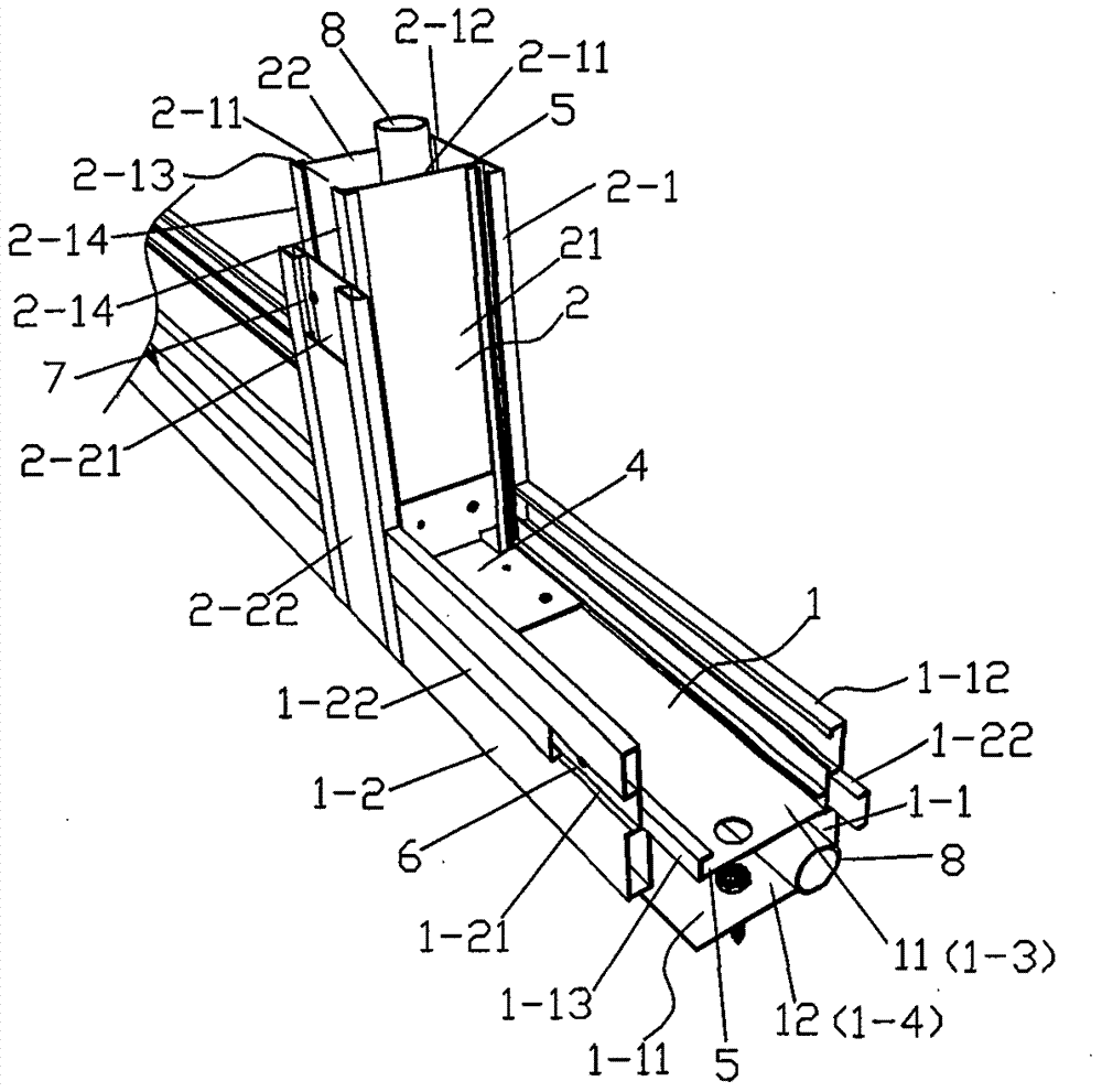
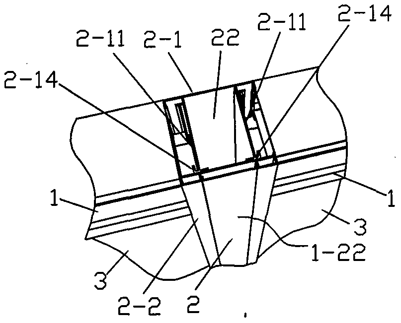
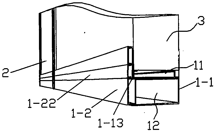
[0022] refer to Figure 1 to Figure 3 A conveniently installed indoor heat insulation and soundproof partition wall includes a beam 1, a central column 2 and a partition 3. The beam 1 is composed of a profile provided with a beam installation groove 11 and a beam line pipe 12. The center column 2 is composed of profiles provided with a center column installation groove 21 and a center column line pipe 22, the beam 1 is a lateral load-bearing beam of a partition wall, and the center column 2 is installed on the beam 1 to form the vertical direction of the beam 1. The support column, the partition plate 3 is installed on the beam installation groove 11 of the beam 1 and the center column installation groove 21 of the center column 2 to form a partition wall, the beam line pipe 12 of the beam 1 and the center column 2 of the beam The column pipes 22 communicate with each other to form a connecting channel for laying water pipes and power lines. The beam installation groove 11 an...


PUM


Abstract

A conveniently installed indoor heat insulation and sound insulation partition wall of the present invention belongs to the field of construction, and belongs to a kind of indoor partition wall, which is used to partition indoor spaces and includes beams, central columns and partitions. The beams are installed by beams. The profile of the groove and the beam line pipeline is composed of the profile of the center column with the center column installation groove and the center column line pipeline. The beam is a lateral load-bearing beam of the partition wall, and the center column is installed on the beam to form a beam The vertical support column body, the partition plate is installed on the beam installation groove of the beam and the center column installation groove of the center column to form a partition wall, and the beam line pipeline of the beam is connected with the center column line pipeline of the center column Form connection channels for laying water pipes and power lines. The invention is simple and convenient to assemble, saves time and effort, and has the characteristics of fast construction speed, good seismic performance, large use area, light building weight, simple construction, flexible assembly, and less labor and materials.

Description

technical field [0001] The invention belongs to the field of construction, and belongs to an indoor partition wall, which is used for partitioning indoor spaces. Background technique [0002] The current partition wall is composed of longitudinal keel, transverse keel and panel, and the panel is fixed on the keel with screws to form a partition wall. The partition wall of this structure needs to be installed with a large number of screws when used, and the existing partition wall The longitudinal keel is installed on one or both sides of the horizontal keel, or the horizontal keel is installed on one or both sides of the longitudinal keel, and the panels are respectively installed on the outside of the vertical and horizontal keel, resulting in thick partition walls and large space occupation, causing indoor The space is difficult to use rationally, and the installation is complicated, time-consuming and labor-intensive, unsightly to use, poor in thermal insulation and sound...

Claims


Application Information

Patent Timeline
Patent Type & Authority Patents(China)
IPC IPC(8): E04B2/74
Inventor 曹友国
Owner GUANGDONG MULIFANG WOODEN HOUSE CO LTD
Why Eureka
Eureka Blog
Learn More