
Large-tonnage beam erection and transportation system in tunnel and beam erection span change procedure thereof

A large-tonnage, tunnel-inside technology, applied in the direction of erecting/assembling bridges, bridges, bridge construction, etc., can solve problems such as difficulties in erecting beams at the entrance and exit of tunnels, erection of box girders in tunnels with difficult bridge machines, etc., and increase equipment stability , High construction efficiency, reduce the effect of side bending

Active Publication Date: 2015-07-08
CHINA RAILWAY ENG MASCH RES & DESIGN INST CO LTD
View PDF6 Cites 15 Cited by
  • Summary
  • Abstract
  • Description
  • Claims
  • Application Information

AI Technical Summary

Problems solved by technology

Most of the existing bridge erecting machines are only suitable for erecting girders in plain areas. At most, beam transport vehicles can directly carry bridge erecting machines or box girders through tunnels. It is difficult to cooperate with bridge erecting machines to realize the erection of box girders in tunnels. Import and export beams are very difficult

Method used


Image

  • Large-tonnage beam erection and transportation system in tunnel and beam erection span change procedure thereof
  • Large-tonnage beam erection and transportation system in tunnel and beam erection span change procedure thereof
  • Large-tonnage beam erection and transportation system in tunnel and beam erection span change procedure thereof

Examples


specific Embodiment approach

[0071] The specific implementation of the beam erection process of the present invention is as follows:

[0072] The basic beam erection operation method is as follows:

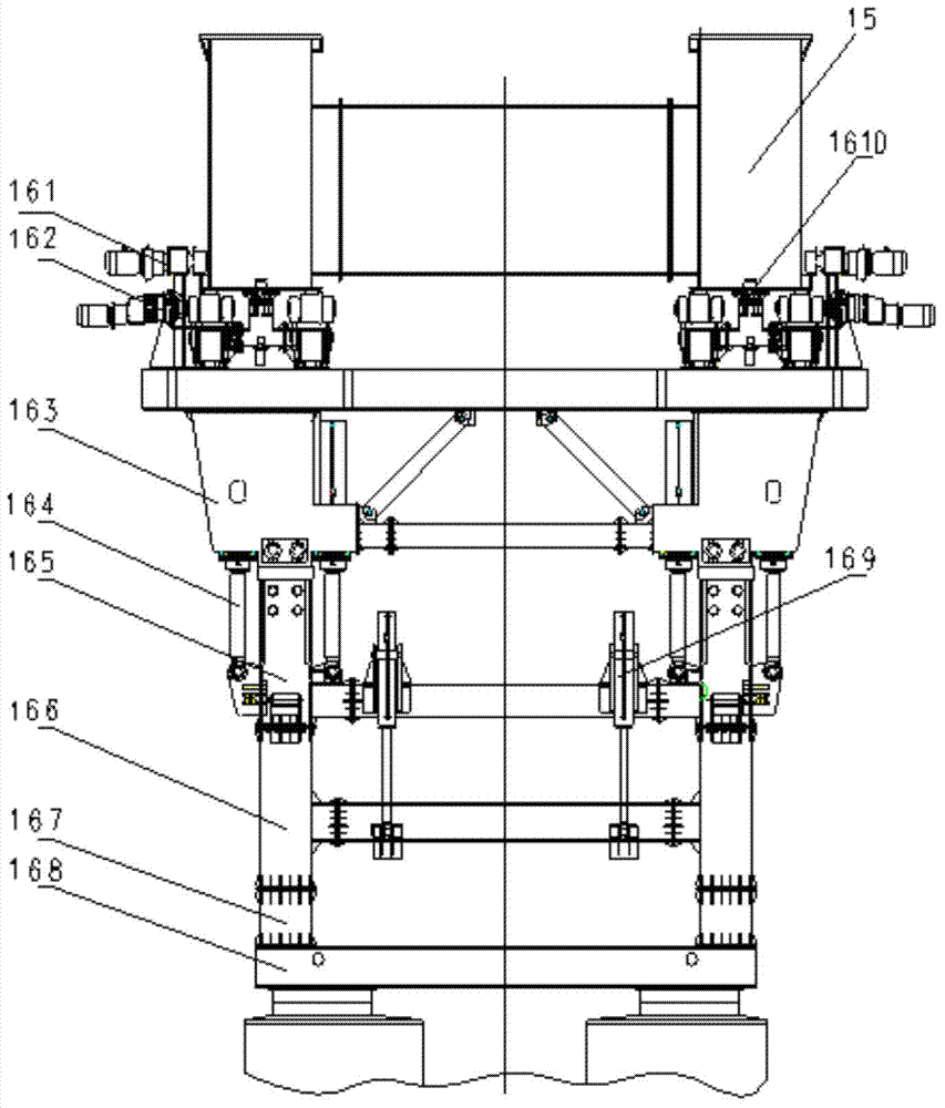
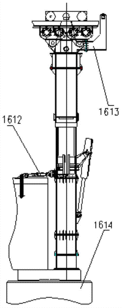
[0073] Step S101, such as Figure 6A As shown, when the beam transport vehicle 2 carries the girder piece 3 to feed the beam, the rear outrigger 11 of the bridge erecting machine is turned over to allow the beam feeding channel. At this time, the bridge erecting machine adopts the front outrigger 16 and the middle outrigger 14;

[0074] Step S102, such as Figure 6B As shown, when the feeding beam is in place, the telescopic legs 21 of the beam transport vehicle are supported on the lower cover plate of the main girder 15 of the bridge erecting machine, and are connected by bolts to form the rear support of the bridge erecting machine. The two trolleys 12 and 13 walk to the position of taking the beam;

[0075] Step S103, such as Figure 6C As shown, the two-stage telescopic columns 146 and 148 on the upp...


PUM


Abstract

The invention discloses a large-tonnage beam erection and transportation system in a tunnel and a beam erection span change procedure thereof, is used for transporting and erecting large prefabricated box beams in high-speed railway and passenger railway lines, and in particular, is suitable for transporting and erecting the box beams in the tunnel. A bridge erection machine comprises main beams, wherein back support legs are arranged at the bottoms of the back ends of the main beams; a downwards recessed front lifting trolley and a back lifting trolley are driven through driving devices by fixed roller chains, are rolled to walk by sliding devices, and are stridden over double main beams; extensible middle support legs are arranged at the bottoms of the middles of the main beams; front support legs capable of moving and extending are arranged at the bottoms of the front ends of the main beams; a beam transporting vehicle comprises a vehicle body; and extension legs, a movable beam support trolley, at least two sets of oil cylinder support legs in the beam support place, multiple wheel sets and front anchor pull rods mounted at the front ends are arranged above the tail end of the vehicle body. The system can satisfy the erection of multiple specifications of passenger railway lines, satisfies the beam erection conditions in tunnel entrances and exits and in the tunnel, simplifies the beam erection procedures, improves the equipment stability, is high in construction efficiency and reasonable and innovative in structural design, and improves the construction efficiency.

Description

technical field [0001] The invention relates to the technical field of railway construction machinery and equipment, in particular to a large-tonnage girder erection frame in a tunnel that is used for the transportation and erection of large prefabricated box girders on high-speed railways or passenger dedicated lines, and is especially suitable for the transportation and erection of box girders in tunnels. The system and its girder spanning process. Background technique [0002] With the continuous deepening of railway construction, there are a large number of bridge-tunnel connection problems, especially in mountainous areas. At the same time, the tunnel may span the karst cave section, and box girders need to be erected in the tunnel. Most of the existing bridge erecting machines are only suitable for erecting girders in plain areas. At most, beam transport vehicles can directly carry bridge erecting machines or box girders through tunnels. It is difficult to cooperate wi...

Claims


Application Information

Patent Timeline
IPC IPC(8): E01D21/06
CPCE01D21/00
Inventor 李维玲王光欣陈家乐王英琳沈超舒俊胡旭东杨旭李国军陈忱
Owner CHINA RAILWAY ENG MASCH RES & DESIGN INST CO LTD
Learn More